Eureka AIR delivers breakthrough ideas for toughest innovation challenges, trusted by R&D personnel around the world.

Road surface casting machine of concrete for municipal engineering construction

A technology for concrete pavement and engineering construction is applied in the field of concrete pavement pouring machines for municipal engineering construction, and can solve the problems of unfavorable pavement construction, poor practicability, and high labor intensity for concrete cutting.

Inactive Publication Date: 2017-10-27
丁家琪
View PDF0 Cites 10 Cited by
  • Summary
  • Abstract
  • Description
  • Claims
  • Application Information

AI Technical Summary

Problems solved by technology

[0003] During the pavement construction process of municipal engineering, we will carry out concrete pouring construction on the pavement. The current construction method usually needs to manually send the shovel to the cavity enclosed by the pavement pouring slab, and then pass the vibrating hammer The vibration causes the concrete to solidify together. In this mode of operation, the labor intensity of concrete blanking is high, and the work efficiency is low, which is not conducive to the construction of the road surface. Although there are also concrete pavement pouring machines in the prior art, although there are also concrete pavement pouring machines in the prior art , but the existing pouring machine will produce uneven pouring during the pouring process, making the upper and lower concrete stratified, which seriously affects the quality of road construction, cannot meet the needs of municipal engineering road construction, and has poor practicability

Method used


Image

  • Road surface casting machine of concrete for municipal engineering construction
  • Road surface casting machine of concrete for municipal engineering construction
  • Road surface casting machine of concrete for municipal engineering construction

Examples


Embodiment Construction

[0022] It should be noted that, in the case of no conflict, the embodiments of the present invention and the features in the embodiments can be combined with each other.

[0023] In describing the present invention, it should be understood that the terms "center", "longitudinal", "transverse", "upper", "lower", "front", "rear", "left", "right", " The orientations or positional relationships indicated by "vertical", "horizontal", "top", "bottom", "inner" and "outer" are based on the orientations or positional relationships shown in the drawings, and are only for the convenience of describing the present invention and Simplified descriptions, rather than indicating or implying that the device or element referred to must have a particular orientation, be constructed and operate in a particular orientation, and thus should not be construed as limiting the invention. In addition, the terms "first", "second", etc. are used for descriptive purposes only, and should not be understood ...


PUM


Abstract

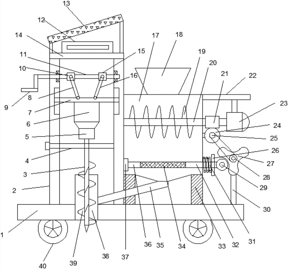
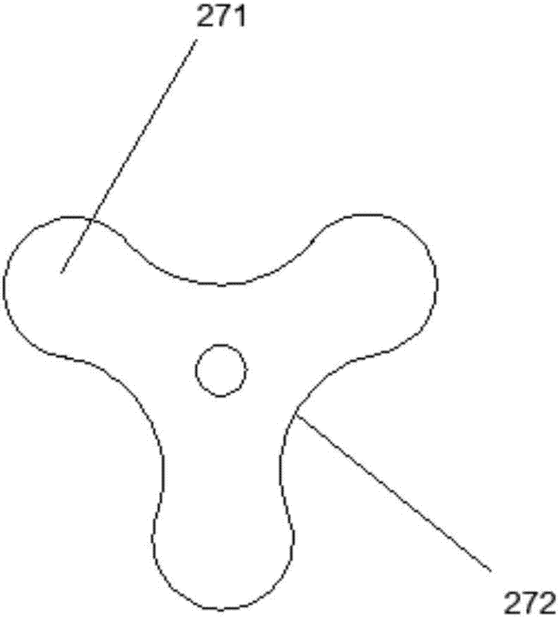
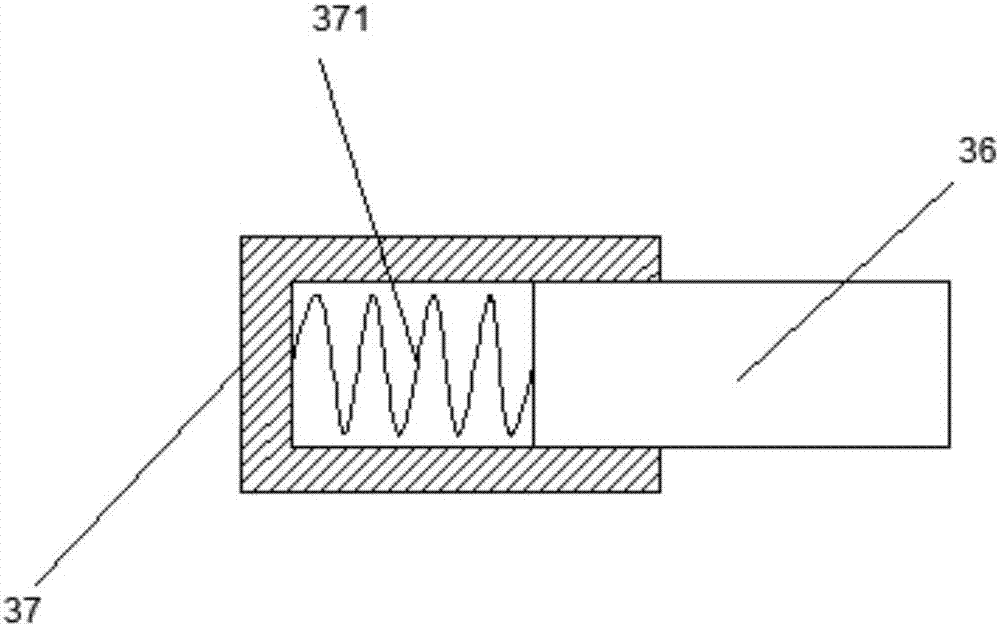
The invention discloses a concrete pavement pouring machine for municipal engineering construction, which comprises a support seat, a support frame is fixedly connected to the left side of the upper end of the support seat, a screw rod is connected to the middle part of the upper end of the support frame, and a lifting plate is connected to the lower ends of the left tie rod and the right tie rod. The middle part of the lower end of the lifting plate is connected with a drive motor, the lower end of the drive motor is connected with a reducer, the reducer is connected with a pouring shaft, the upper end of the support seat is connected with a support leg, the upper end of the support leg is connected with a concrete box, and the upper end of the concrete box is connected with a stirring shaft , the right end of the stirring shaft is connected with a worm, the lower end of the worm is meshed with a worm wheel, the middle part of the worm wheel is connected with a driving pulley coaxially, the driving pulley is connected with a driven pulley through a belt, and the middle part of the driven pulley is connected with a Y-shaped cam at a coaxial position . The invention realizes the uniform feeding of the concrete in the concrete box, and also realizes the lifting type mixing of the concrete during the pouring process, and avoids the upper and lower stratification of the concrete.

Description

technical field [0001] The invention relates to the technical field of municipal engineering equipment, in particular to a concrete pavement pouring machine for municipal engineering construction. Background technique [0002] In my country, municipal facilities refer to various buildings, structures, equipment, etc. that are set up within the planning and construction scope of urban areas, towns (townships), and provide residents with paid or unpaid public products and services based on government responsibilities and obligations. The construction of various public infrastructure supporting urban life belongs to the category of municipal engineering, such as common urban roads, bridges, subways, such as various pipelines closely related to life: rainwater, sewage, water supply, reclaimed water, electricity (outside the red line) Partial), telecommunications, heat, gas, etc., as well as the construction of squares, urban greening, etc., all belong to the category of municipa...

Claims


Application Information

Patent Timeline
Patent Type & Authority Applications(China)
IPC IPC(8): E01C19/47
CPCE01C19/47
Inventor 丁家琪
Owner 丁家琪
Why Eureka
Eureka Blog
Learn More