Crack repairing device for reinforced concrete drainage pipe manufacturing
A technology for repairing reinforced concrete and cracks, which is applied to the devices, pipes, and rigid pipes that apply liquid to the surface. It can solve the problems of frequent glue injection, large amount of glue injection, and difficulty in cleaning dust and concrete debris. Improve the efficiency of glue injection, reduce the strength of glue injection, and facilitate the replacement of glue barrels
- Summary
- Abstract
- Description
- Claims
- Application Information
AI Technical Summary
Problems solved by technology
Method used
Image
Examples
Embodiment 1
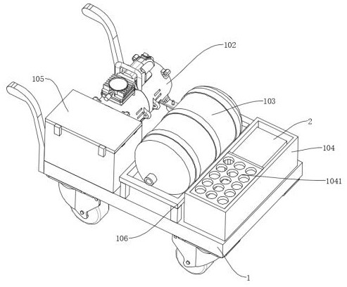
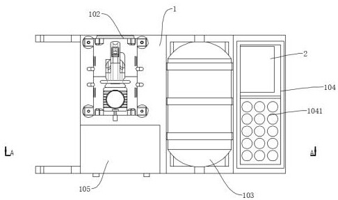
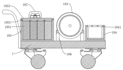
[0035] Such as Figure 1-7 As shown, a crack repairing device made of reinforced concrete drainage pipes includes a mobile cart 1, and the top of the mobile cart 1 is connected with an air compressor 102, a placement box 104, an electric box 105 and a support frame 106 by bolts, and the support frame 106 The top is connected with an air storage tank 103 by bolts, and the outlet end of the air compressor 102 communicates with the air storage tank 103 through a gas pipe. There are two chambers inside the storage box 104, and the inside of the two chambers are respectively provided with a plastic barrel storage rack 1041 And the repairing mechanism 2, the repairing mechanism 2 is connected with the gas storage tank 103 through the air pipe, the inside of the electric box 105 is provided with a battery 1051, and the battery 1051 is connected with the air compressor 102 through wires, so that the battery 1051 can be used to provide electric current for the air compressor 102 , the ...
Embodiment 2
[0038] Such as Figure 8 As shown, the difference between Embodiment 2 and Embodiment 1 is that: a tension spring 218 is sheathed on the outside of the fixed rod 2163, one end of the tension spring 218 is hung under the glue injection head 216, and the other end is set on the top of the rotating plate 2164, so that The setting can pull the rotating plate 2164 through the tension spring 218, and the rotating plate 2164 drives the injection nozzle 2165 to move, so that the non-working injection nozzle 2165 is close to the injection head 216, preventing the non-working injection nozzle 2165 from affecting the working injection nozzle 2165 Work.
[0039] In the above structure, when in use, first move the entire device to a suitable displacement, then start the air compressor 102, the air compressor 102 generates pressurized gas, and the pressurized gas is stored inside the gas storage tank 103, when working, firstly from Take out the rubber bucket in the rubber bucket placement ...
PUM
 Abstract
Description
Claims
Application Information
 - R&D
- Intellectual Property
- Life Sciences
- Materials
- Tech Scout
- Unparalleled Data Quality
- Higher Quality Content
- 60% Fewer Hallucinations
Browse by: Latest US Patents, China's latest patents, Technical Efficacy Thesaurus, Application Domain, Technology Topic, Popular Technical Reports.
© 2025 PatSnap. All rights reserved.Legal|Privacy policy|Modern Slavery Act Transparency Statement|Sitemap|About US| Contact US: help@patsnap.com


