Broadband folding type plane reflection array antenna

A planar reflection, array antenna technology, applied in the direction of antenna, antenna array, specific array feeding system, etc., can solve the problems of increasing the complexity of the feeding network, affecting the radiation efficiency of the antenna, increasing the transmission loss of the feeding Flat phase curve, large phase shift range, and good broadband performance

Pending Publication Date: 2021-06-22
NANJING UNIV OF SCI & TECH
View PDF1 Cites 3 Cited by
  • Summary
  • Abstract
  • Description
  • Claims
  • Application Information

AI Technical Summary

Problems solved by technology

Since the feed network of the phased array antenna uses a large number of phase shifters and amplifiers, the complexity of the feed network will increase significantly with the expansion of the array size, resulting in increased feed transmission loss and affecting the overall radiation efficiency of the antenna.
Moreover, the complex feed network makes the cost of the antenna rise significantly

Method used


Image

  • Broadband folding type plane reflection array antenna
  • Broadband folding type plane reflection array antenna
  • Broadband folding type plane reflection array antenna

Examples


Embodiment

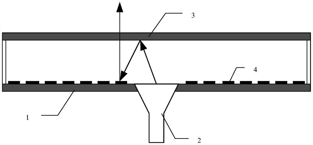
[0035] Such as figure 1 , figure 2 As shown, a broadband folded plane reflective array antenna, including a dielectric substrate 1, a feed horn 2, a polarized grid 3, and a large amount of reflective unit 4 printed on the dielectric substrate; the polarization grid 3 parallel Above the medium substrate, the height h = 25 mm from the dielectric substrate. The feed horn 2 is mounted at the center gap of the dielectric substrate, and the electromagnetic wave emitted by the feed speaker is irradiated to the medium substrate after the upper polarization grid, and the reflection unit is adjusted to the polarization through the reflection unit through the dielectric substrate. Reflected into a planar wave and transmitted from the polarized grid, realization of a high gain and a low sub-petter beam.

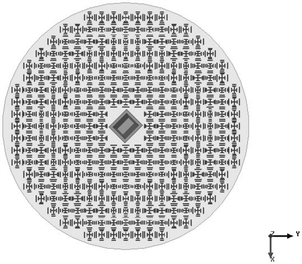
[0036] image 3 The structural diagram of the reflective array plate of the present invention is given. The dielectric substrate is a circular structure, a diameter of 90 mm, a large amount ...


PUM


Abstract

The invention discloses a broadband folding plane reflection array antenna which comprises a dielectric substrate, a feed horn, a polarization grid and a large number of reflection units printed on the dielectric substrate, wherein each reflection unit adopts a double-resonant structure and is composed of a Jerusalem cross patch arranged in the center and two pairs of rectangular patches arranged on the periphery, the unit has a flat phase shift curve and a phase shift range exceeding 450 degrees, so that the broadband performance of the antenna is realized. The broadband folding type plane reflection array antenna is simple in structure, low in profile, good in mechanical stability and free of shielding of a feed source and a support.

Description

Technical field [0001] The present invention relates to the field of microwave millimeter wave antenna, particularly a broadband folded flat reflection array antenna. [0002] technical background [0003] In recent years, with the continuous development of wireless communication technology, high-gain antennas play an increasingly important role in satellite communications, deep space detection and long-distance communications. Traditional high gain antennas are mainly parabolic antennas and planar phased array antennas, although the parabolic antenna has the advantages of simple structure, bandwidth, high gain, good direction, but it also has a lot of shortcomings. The surface structure inherent in the parabolic antenna causes the antenna size and cumbersome, not convenient for installation and transportation, and high requirements for machining accuracy, especially in millimeter bars. In addition, the parabolic antenna function is single, and the beam design is not flexible. The...

Claims


Application Information

Patent Timeline
Patent Type & Authority Applications(China)
IPC IPC(8): H01Q21/00H01Q1/50H01Q15/14H01Q19/10
CPCH01Q21/00H01Q21/0006H01Q1/50H01Q19/10H01Q15/14
Inventor 齐世山孙勇吴文黄慧周恬
Owner NANJING UNIV OF SCI & TECH
Why Eureka
Try Eureka