Calculation method and device for dynamic delay time of exhaust gas recirculation system

A recirculation system and dynamic delay technology, applied in electrical control, engine control, machine/engine, etc., can solve the problems of EGR rate calculation lag, difficulty in fully exerting EGR fuel-saving effect, and inaccurate calculation of engine EGR gas volume. Achieve the effect of improving performance and utilization, and improving the accuracy of calculation results

Active Publication Date: 2022-06-21
GUANGZHOU AUTOMOBILE GROUP CO LTD
View PDF5 Cites 0 Cited by
  • Summary
  • Abstract
  • Description
  • Claims
  • Application Information

AI Technical Summary

Problems solved by technology

And after the mixing valve performs the action, it will take a certain time for the vacuum degree of the mixing place to be established, resulting in a delay in the change of the EGR rate at the mixing point compared with the action of the EGR valve / mixing valve
This makes the EGR rate in the mixing chamber and the EGR rate in the cylinder asynchronous in time during the dynamic process of the engine, that is, there is a dynamic delay time, which will lead to a serious lag in the calculation of the EGR rate in the dynamic process of the engine and cannot be accurate. Calculating the amount of EGR gas actually entering the cylinder at the current moment of the engine is difficult to fully exert the fuel-saving effect of EGR, which directly affects the effect of this technology on the actual vehicle

Method used


Image

  • Calculation method and device for dynamic delay time of exhaust gas recirculation system
  • Calculation method and device for dynamic delay time of exhaust gas recirculation system
  • Calculation method and device for dynamic delay time of exhaust gas recirculation system

Examples


Embodiment 1

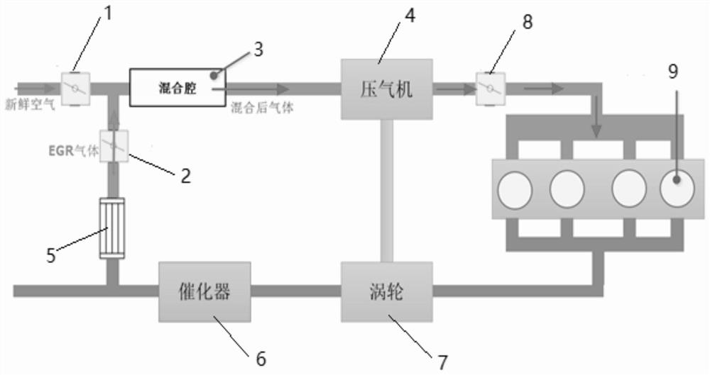
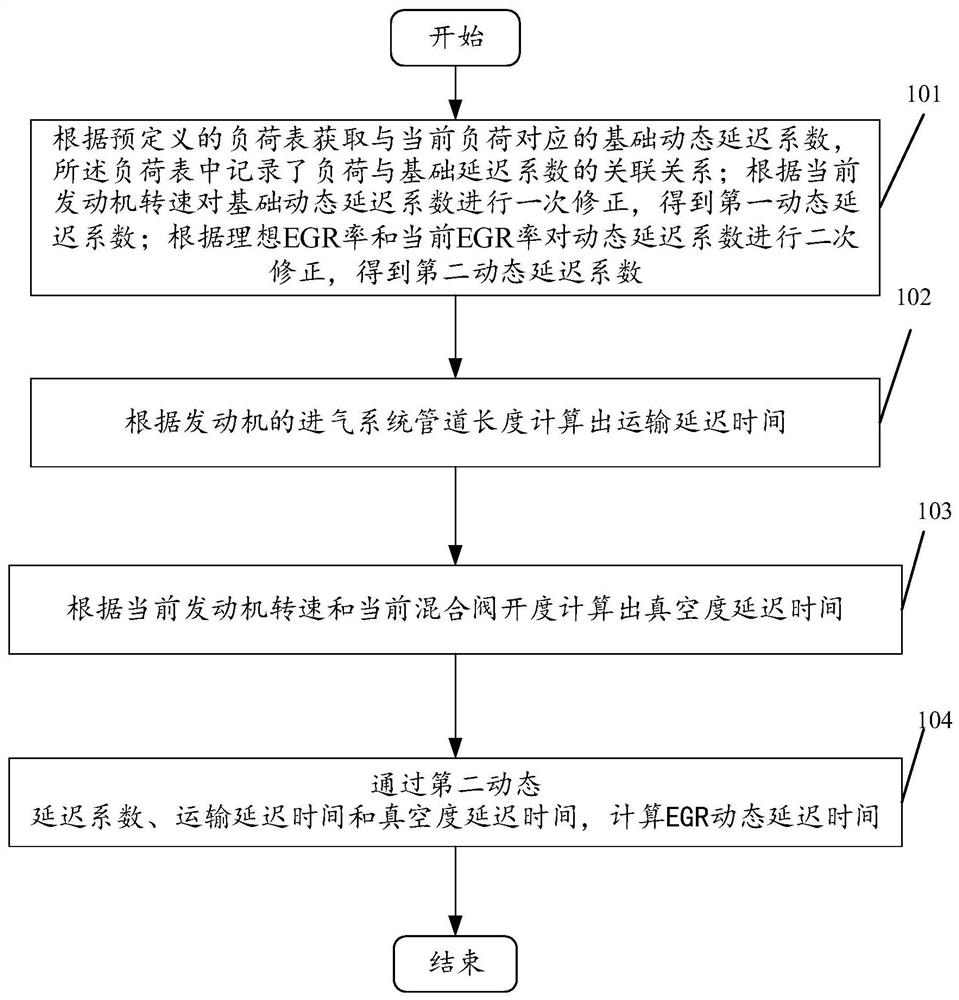
[0073] see image 3 , image 3 This is a schematic flowchart of a method for calculating a dynamic delay time of an exhaust gas recirculation system disclosed in an embodiment of the present invention. in, image 3 The described method can be applied to an exhaust gas recirculation system, the exhaust gas recirculation system includes a mixing valve, an EGR valve and a mixing chamber, and the fresh air output from the mixing valve and the EGR gas output from the EGR valve are mixed in the mixing chamber and then output to the mixing chamber. In the compressor, other structures or systems capable of mixing the fresh air output by the mixing valve with the EGR gas output by the EGR valve are not limited in the embodiments of the present invention. like image 3 As shown, the method for calculating the dynamic delay time of the exhaust gas recirculation system may include the following operations:

[0074] 101. Obtain the basic dynamic delay coefficient corresponding to the c...

Embodiment 2

[0130] see Figure 4 , Figure 4 The described method can be applied to an exhaust gas recirculation system, the exhaust gas recirculation system includes a mixing valve, an EGR valve and a mixing chamber, and the fresh air output from the mixing valve and the EGR gas output from the EGR valve are mixed in the mixing chamber and then output to the mixing chamber. The compressor, wherein other structures or systems capable of mixing the fresh air output by the mixing valve with the EGR gas output by the EGR valve are not limited in the embodiments of the present invention. like Figure 4 As shown, the method for calculating the dynamic delay time of the exhaust gas recirculation system may include the following operations:

[0131] 201. Obtain a basic dynamic delay coefficient corresponding to the current load according to a predefined load table, in which the load table records the relationship between the load and the basic delay coefficient; perform a correction on the bas...

Embodiment 3

[0193] see Figure 5 , Figure 5 A block diagram of a calculation flow of an EGR dynamic delay time disclosed in an embodiment of the present invention. in, Figure 5 The described method can be applied to an exhaust gas recirculation system, the exhaust gas recirculation system includes a mixing valve, an EGR valve and a mixing chamber, and the fresh air output from the mixing valve and the EGR gas output from the EGR valve are mixed in the mixing chamber and then output to the compressed air. The embodiment of the present invention is not limited to other structures or systems capable of mixing the fresh air output by the mixing valve with the EGR gas output by the EGR valve. As shown in the figure, the specific implementation is as follows:

[0194] Step (1): First, obtain the basic dynamic delay coefficient corresponding to the current load according to a predefined load table, in which the relationship between the load and the basic delay coefficient is recorded; the b...


PUM


Abstract

The invention discloses a method and device for calculating the dynamic delay time of an exhaust gas recirculation system. The method includes: obtaining a basic dynamic delay coefficient corresponding to the current load according to a predefined load table; and correcting the basic dynamic delay coefficient once according to the current engine speed , to obtain the first dynamic delay coefficient; according to the ideal EGR rate and the current EGR rate, the first dynamic delay coefficient is corrected twice to obtain the second dynamic delay coefficient; the transportation delay time is calculated according to the length of the engine intake system pipeline; according to The vacuum degree delay time is calculated by the current engine speed and the current mixing valve opening degree; the EGR dynamic delay time is calculated according to the second dynamic delay coefficient, the transport delay time and the vacuum degree delay time. The technical solution can calculate and obtain the EGR rate through the obtained EGR dynamic delay time, thereby improving the accuracy of the calculation result of the EGR rate of the gas in the engine cylinder, thereby improving the engine performance.

Description

technical field [0001] The invention relates to the technical field of engine control, in particular to a method and device for calculating the dynamic delay time of an exhaust gas recirculation system. Background technique [0002] EGR (Exhaust Gas Recirculation, exhaust gas recirculation) technology is currently a hot technology for engine energy saving and emission reduction. In practical application, the flow of fresh air in the exhaust gas recirculation system is controlled by the mixing valve, and the flow of EGR gas is controlled by the EGR valve. After the mixing chamber is mixed, it becomes a mixture of fresh air and EGR gas. The ratio of EGR gas in this gas, that is, the EGR rate, is a key parameter affecting the combustion process. [0003] However, the technical personnel of the present invention found in the research that due to the long pipeline of the intake system, it takes a certain time for the mixed gas to control the EGR rate by the mixing valve / EGR valve...

Claims


Application Information

Patent Timeline
Patent Type & Authority Patents(China)
IPC IPC(8): F02D41/00
CPCF02D41/0047F02D2200/04F02D2200/101
Inventor 刘巨江何宇连学通
Owner GUANGZHOU AUTOMOBILE GROUP CO LTD
Why Eureka
Try Eureka