
Novel multifunctional combined system maritime work structure

A multi-functional combination, marine structure technology, applied in marine engineering, water conservancy engineering, coastline protection and other directions, can solve the problems of structural enhancement, overall structure strengthening, large size of wave-proof board, etc., to optimize structural design and reduce structural stress. Effect

Inactive Publication Date: 2021-06-22
CCCC FHDI ENG
View PDF5 Cites 3 Cited by
  • Summary
  • Abstract
  • Description
  • Claims
  • Application Information

AI Technical Summary

Problems solved by technology

However, the existing pile-based permeable breakwater considers the combination of pile foundation and wave-proof board, which is suitable for projects with small wave periods and wave heights. For sea areas with medium-to-long-period waves or large waves, the wave-blocking effect is poor, and the bottom of the wave-proof board The elevation needs to be close to the original mud surface to meet the small wave transmission, which makes the size of the anti-wave plate larger, resulting in an increase in the wave load on it, and the overall structure needs to be strengthened, resulting in difficulty in construction and installation, and high cost
In addition, in order to avoid the influence of over-waves and water level changes on the operation of the wharf, the elevation of the wharf surface is generally set higher, which makes it difficult for ships to berth; on the other hand, the internal force of the pile foundation increases, the structure strengthens, and the project cost increases

Method used


Image

  • Novel multifunctional combined system maritime work structure
  • Novel multifunctional combined system maritime work structure
  • Novel multifunctional combined system maritime work structure

Examples


Embodiment Construction

[0029] In order to more clearly understand the above objects, features and advantages of the present invention, the present invention will be further described in detail below in conjunction with the accompanying drawings and specific embodiments. structure, so it only shows the configuration related to the present invention, and it should be noted that, in the case of no conflict, the embodiments in the present application and the features in the embodiments can be combined with each other.

[0030] In the following description, many specific details are set forth in order to fully understand the present invention, but the present invention can also be implemented in other ways different from those described here, therefore, the protection scope of the present invention is not limited by the specific implementation disclosed below. Example limitations.

[0031] In the description of the present application, it should be understood that the terms "center", "longitudinal", "tra...


PUM


Abstract

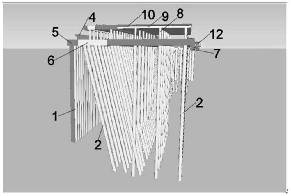
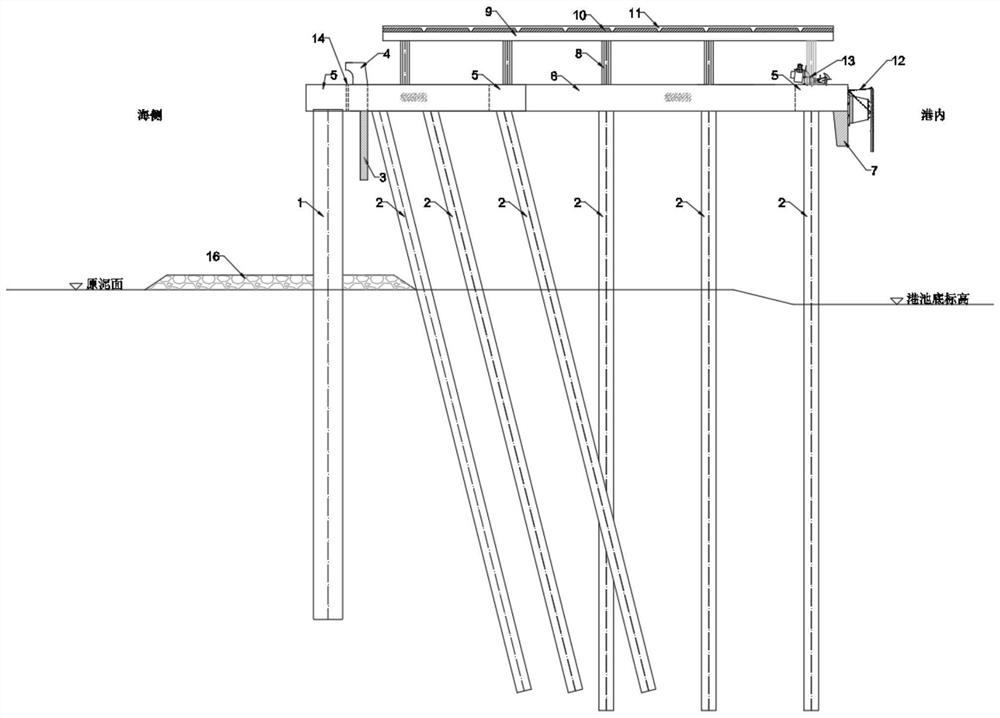
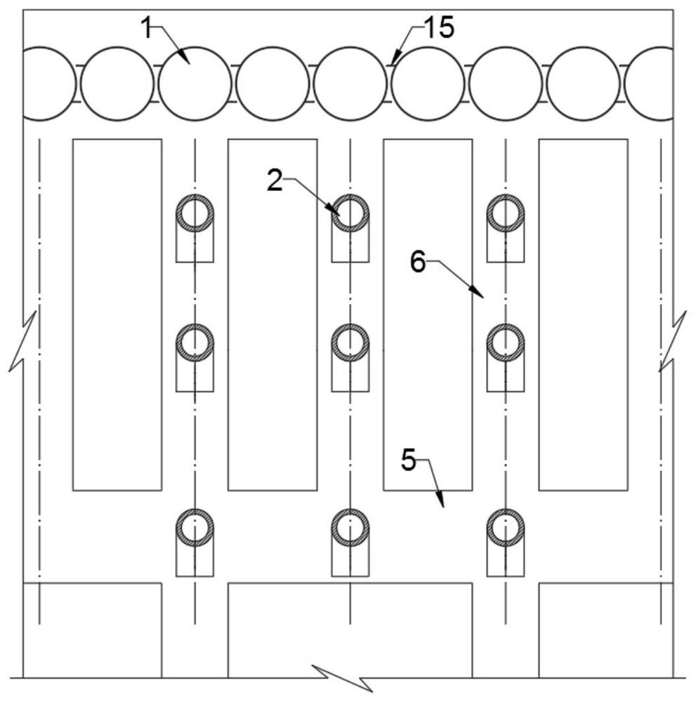
The invention relates to a novel multifunctional combined system maritime work structure. The novel multifunctional combined system maritime work structure comprises a seaside wave blocking system, a port inner side lower layer system, a berthing system and an upper layer wharf operation platform system; the seaside wave blocking system is formed by arranging a plurality of densely-arranged piles at equal intervals; rib plates are arranged on the two sides of the densely-arranged piles; the tops of the densely-arranged piles are connected into a whole through longitudinal beams; the longitudinal beams are provided with reverse arc retaining walls; wave blocking plates are arranged below the reverse arc retaining walls; a plurality of water permeable holes are formed in the longitudinal beams on the seaside; bottom protecting structures are arranged on the mud faces of the densely-arranged piles; the port inner side is of a double-layer frame combined structure; the lower layer system and the berthing system are provided with a plurality of cross beams to form a whole with the densely-arranged piles; the longitudinal beams are arranged at the two ends and the middle of the cross beams to form a beam grid structure; the beam grid structure can also serve as a lower layer traffic and maintenance channel; a plurality of rows of pile foundations with different slopes are arranged below the beam grid structure and distributed in the length direction of the cross beams; the port inner side cross beams are provided with berthing components which can also serve as the wave blocking plates; and meanwhile, system and berthing ancillary facilities and safety facilities are arranged.

Description

technical field [0001] The invention relates to the field of civil engineering construction, in particular to a novel multifunctional combined system marine structure. Background technique [0002] With the development of large-scale ships and the continuous large-scale development and utilization of coastal natural resources, the resources of good harbors are exhausted. Therefore, new ports have to be developed in sea areas with poor shelter conditions and constructed in open seas with deep water, large waves, and complex geological conditions. Docks became an inevitable trend. In order to ensure the operating time and safety of the ship and the safety of the wharf structure, the existing port is usually designed with a breakwater to form a good shelter condition, and the wharf is separated from the breakwater to reduce the impact of the breakwater’s overtaking and wave force on the wharf. The cost of port engineering construction is relatively high. Traditional sloping b...

Claims


Application Information

Patent Timeline
IPC IPC(8): E02B3/06
CPCE02B3/068
Inventor 丁建军李少斌张勇詹广才周野牛红林潘跃鹏谭彬政林冠堃
Owner CCCC FHDI ENG
Learn More