


Quick Research
Generate reliable direction feasibility study reports for your R&D in just a few steps.

Technical Q&A
Discover and master advanced knowledge NOW. Basics, ideas, possibilities, all at once.

Find Solutions
As an expert in R&D theories, this can generate solutions to your technical problems instantly.

Evaluate Feasibility
Analyze your overall solution with one click, know your potential R&D risks in advance.

Monitor Landscape
Get weekly tech updates, stay abreast of the latest tech innovations and key insights.
Buried pipeline dredger
A technology for buried pipelines and dredges is applied in chemical instruments and methods, cleaning hollow objects, cleaning methods and utensils, etc. It can solve the problems of inadequate protection of buried pipelines, easy entry into concrete, pipeline blockage, etc. effect, convenient replacement, and improved applicability
- Summary
- Abstract
- Description
- Claims
- Application Information
AI Technical Summary
Problems solved by technology
Method used
Image

Examples
Embodiment 1
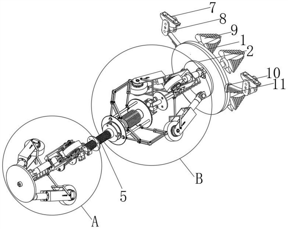
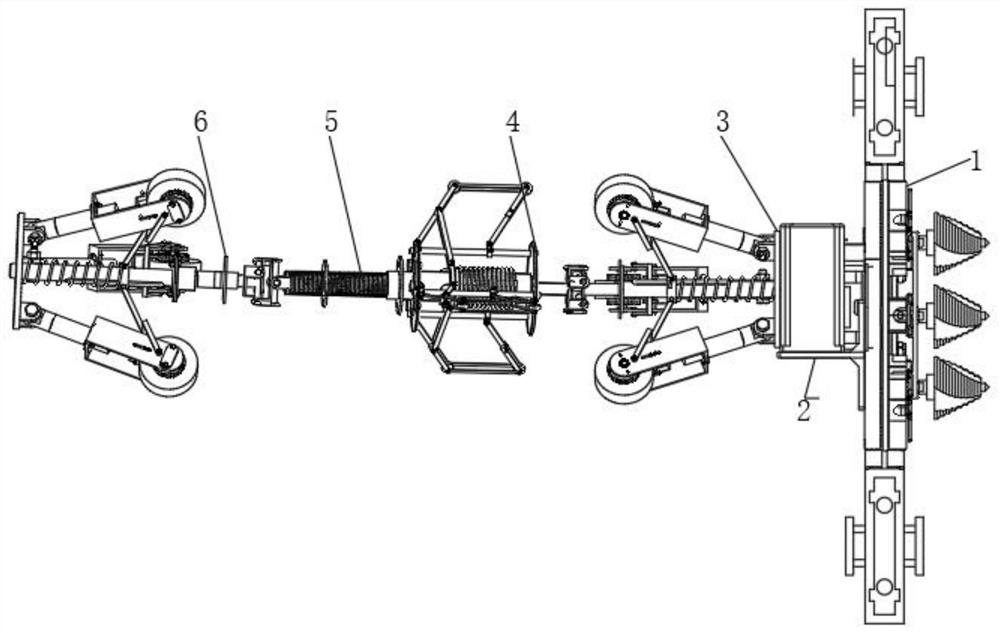
[0029] see Figure 1-8, the buried pipeline dredger according to the preferred embodiment of the present invention includes a crushing structure 1, a driving source structure 2 is arranged on one side of the crushing structure 1, and a first driving structure 3 is fixedly installed on the side of the driving source structure 2 away from the crushing structure 1 . The side of the first driving structure 3 away from the driving source structure 2 is fixedly connected with a guide structure 4, and the side of the guiding structure 4 away from the first driving structure 3 is fixedly connected with a strong spring one 5, and the strong spring one 5 is away from one side of the guiding structure 4 The side is fixedly connected with a third drive structure 6 . The crushing structure 1 includes a ring plate 15, and the side of the ring plate 15 away from the driving source structure 2 is circular and equidistantly fixedly installed with eight pressing structures 16, and the clamping...
Embodiment 2
[0033] In a preferred embodiment, the first drive structure 3 is consistent with the structure of the third drive structure 6, the third drive structure 6 includes a circular plate-25, and a slide bar-1 is fixedly installed at the center of the circle on one side of the circular plate-25. 29. One end of slide bar one 29 is fixedly connected with circular plate two 30, and one side of circular plate two 30 is fixedly equipped with three hinged seats one 31, and circular plate two 30 is connected with rotating block 32 by hinged seat one 31 rotations. One end of the rotating block 32 is fixedly connected with a fixed column 33, and one end of the fixed column 33 is fixedly connected with a U-shaped frame 34, and the inner chamber of the U-shaped frame 34 is rotatably equipped with a guide wheel 36, and the driving end of the guide wheel 36 is fixedly connected There are servo motors.
[0034] Further, the outer wall of U-shaped frame 34 is rotatably installed with mounting shaf...
Embodiment 3
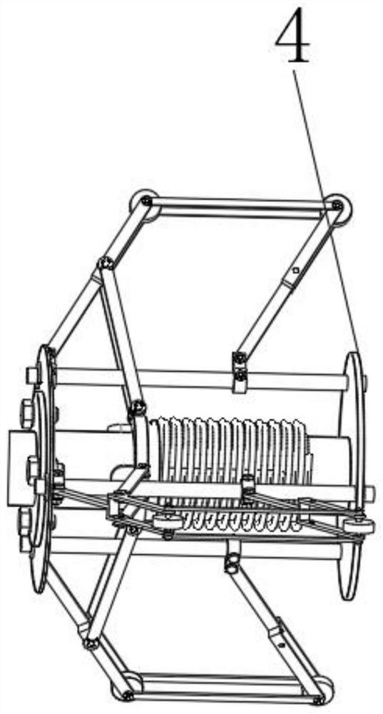
[0036] Further, the guide structure 4 includes a circular plate 39, the center of the circle on one side of the circular plate 39 is fixedly connected with a slide bar 3 53, and one end of the slide bar 3 53 is fixedly connected with a circular plate 440, and the circular plate 39 and the circular plate Three sliding sleeves three 41 are fixedly installed between the opposite faces of four 40. The outer wall of the sliding rod three 53 is slidingly installed with a sliding sleeve three 41, the outer wall of the sliding rod three 53 is located between the sliding sleeve three 41 and the circular plate three 39, and a strong spring three 43 is installed on the outer wall, and the outer wall of the sliding sleeve three 41 is fixedly installed There are three sets of bumps three 51 .
[0037] Further, the side of the fourth circular plate 40 close to the third circular plate 39 is fixedly installed with three sets of hinged seats 2 42 , and the fourth circular plate 40 is installe...
PUM
 Abstract
Description
Claims
Application Information
 - R&D Engineer
- R&D Manager
- IP Professional
- Industry Leading Data Capabilities
- Powerful AI technology
- Patent DNA Extraction
Browse by: Latest US Patents, China's latest patents, Technical Efficacy Thesaurus, Application Domain, Technology Topic, Popular Technical Reports.
© 2024 PatSnap. All rights reserved.Legal|Privacy policy|Modern Slavery Act Transparency Statement|Sitemap|About US| Contact US: help@patsnap.com