Micro projection display device and AR display system with same

A display device and micro-projection technology, which is applied in projection devices, instruments, optics, etc., can solve the problems of difficulty in making micro- and micro-projectors large in size and inconvenient to carry, and achieve convenient miniaturized design, flattening of space volume, The effect of reducing space waste

Pending Publication Date: 2021-06-18
HANGZHOU LINGBAN TECH CO LTD
View PDF0 Cites 1 Cited by
  • Summary
  • Abstract
  • Description
  • Claims
  • Application Information

AI Technical Summary

Problems solved by technology

At present, LCOS micro-projectors generally include a projection lighting system, a PBS polarizing beam splitter, an LCOS imaging chip, and a projection lens. Usually, the projection lighting system and the PBS polarizing beam splitting prism are located in the first direction, while the LCOS imaging chip, PBS polarizing beam splitting prism, and projection lens Located in the second direction, and the first direction is perpendicular to the second direction, since the volume of the projection lighting system and the projection lens are large, when the projection lighting system and the projection lens are vertically arranged, there is a gap between the projection lighting system and the projection lens The space is empty, resulting in a lot of waste of space. At the same time, it leads to a large size of the micro-projector, which is difficult to be miniaturized, not easy to carry, and not easy to cut into the AR display system. When cutting into the AR display system, additional optical path design is required. A right-angle prism is set to reflect the polarized light passing through the LCOS imaging chip and projection lens to the optical waveguide, resulting in a very complicated structure

Method used


Image

  • Micro projection display device and AR display system with same
  • Micro projection display device and AR display system with same
  • Micro projection display device and AR display system with same

Examples


Embodiment Construction

[0021] In order to further explain the technical means and effects of the present invention to achieve the intended purpose of the invention, the specific implementation, structure, features and effects of the micro-projection display device proposed according to the present invention will be described below in conjunction with the accompanying drawings and preferred embodiments. , as detailed below.

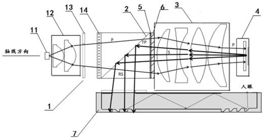
[0022] figure 1 It is a schematic structural diagram of a micro projection display device according to the first embodiment of the present invention;

[0023] figure 2 It is a schematic structural diagram of the AR display system according to the first embodiment of the present invention; image 3 It is a schematic structural diagram of a micro-projection display device and an AR display system according to a second embodiment of the present invention; Figure 4 It is a schematic structural diagram of a micro-projection display device and an AR display system according to a ...


PUM


Abstract

The invention relates to a micro projection display device which is characterized by comprising a projection light source, a PBS prism, a projection lens module and an LCOS imaging chip, wherein the projection light source is used for emitting first polarized light; the PBS prism is used for transmitting first polarized light emitted by the projection light source to the projection lens module; the projection lens module is used for focusing the first polarized light transmitted by the PBS prism to the LCOS imaging chip; the LCOS imaging chip is used for modulating the first polarized light focused by the projection lens module into second polarized light and emitting the modulated second polarized light to the PBS prism; the PBS prism is also used for reflecting the second polarized light emitted by the LCOS imaging chip; the projection light source, the PBS prism, the projection lens module and the LCOS imaging chip are sequentially arranged along an axis.

Description

technical field [0001] The invention relates to the technical field of micro-projectors, in particular to a micro-projection display device and an AR display system having the same. Background technique [0002] The core of the design of the micro projection device is to use as few lenses as possible to meet the image quality requirements while ensuring a small size. At present, LCOS micro-projectors usually include a projection lighting system, a PBS polarizing beam splitter, an LCOS imaging chip, and a projection lens. Usually, the projection lighting system and the PBS polarizing beam splitting prism are located in the first direction, while the LCOS imaging chip, PBS polarizing beam splitting prism, and projection lens Located in the second direction, and the first direction is perpendicular to the second direction, since the volume of the projection lighting system and the projection lens are large, when the projection lighting system and the projection lens are vertica...

Claims


Application Information

Patent Timeline
Patent Type & Authority Applications(China)
IPC IPC(8): G03B21/20
CPCG03B21/2033G03B21/2073
Inventor 许礼强程琳管亮秦建涛吴险峰
Owner HANGZHOU LINGBAN TECH CO LTD
Why Eureka
Try Eureka