
Optical module

A technology of optical modules and side panels, which is applied in the field of optical communications, can solve problems such as waste of circuit board space, and achieve the effect of reducing waste

Inactive Publication Date: 2020-05-19
HISENSE BROADBAND MULTIMEDIA TECH
View PDF5 Cites 5 Cited by
  • Summary
  • Abstract
  • Description
  • Claims
  • Application Information

AI Technical Summary

Problems solved by technology

However, whether it is the screw locking method or the bump pressing plate fixing method, it is necessary to reserve a pressing plate area on the circuit board for pressing the screws or bumps, which will easily cause waste of space on the circuit board

Method used


Image

  • Optical module
  • Optical module
  • Optical module

Examples


Embodiment Construction

[0025] The following will clearly and completely describe the technical solutions in the embodiments of the present invention with reference to the accompanying drawings in the embodiments of the present invention. Obviously, the described embodiments are only some, not all, embodiments of the present invention. Based on the embodiments of the present invention, all other embodiments obtained by persons of ordinary skill in the art without creative efforts fall within the protection scope of the present invention.

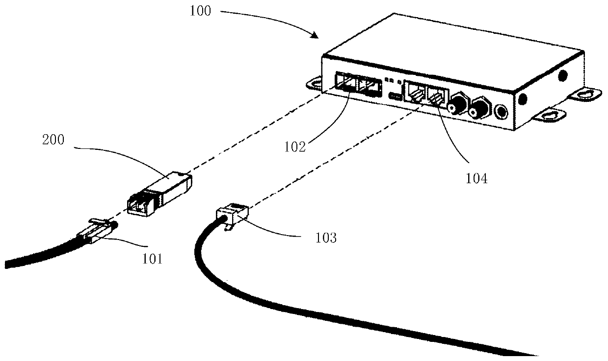
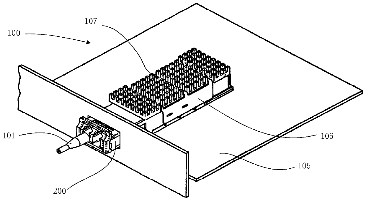
[0026] One of the core links of optical fiber communication is the mutual conversion of optical and electrical signals. Optical fiber communication uses optical signals carrying information to be transmitted in information transmission equipment such as optical fibers / optical waveguides, and the passive transmission characteristics of light in optical fibers / optical waveguides can be used to achieve low-cost, low-loss information transmission; and information proces...


PUM


Abstract

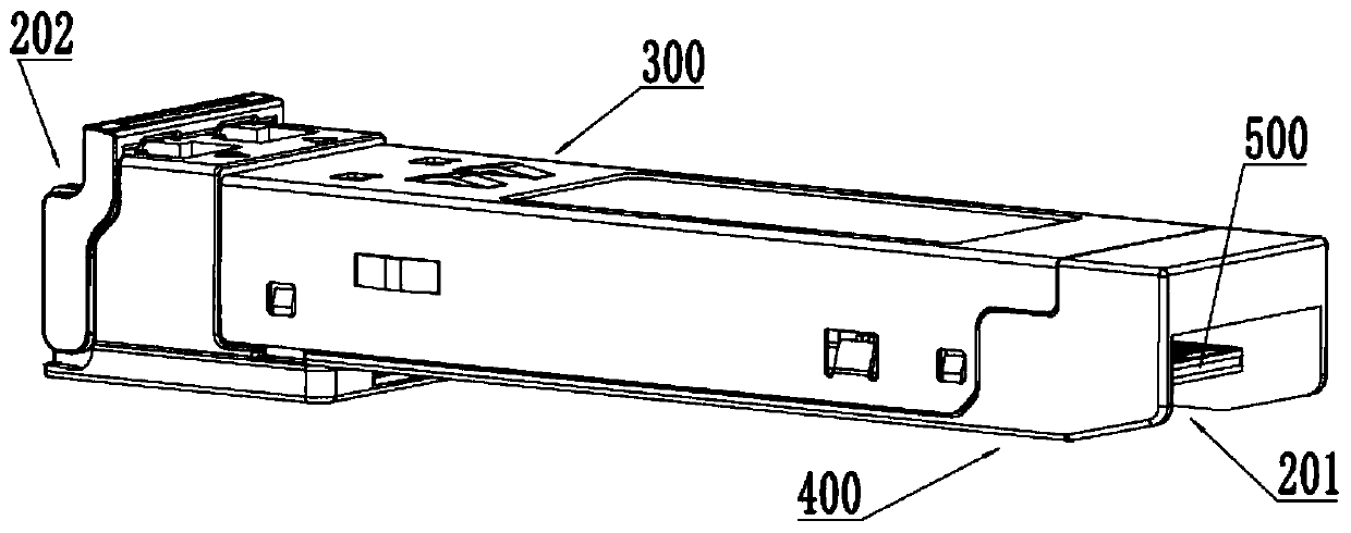
The invention provides an optical module. The optical module comprises an upper shell, a lower shell and a circuit board, wherein the upper shell comprises a cover plate, a first side plate and a second side plate, the first side plate and the second side plate are arranged at two opposite sides of the cover plate and are fixedly connected, the first side plate and the second side plate are respectively provided with an extrusion part, the extrusion part on the first side plate inclines towards the second side plate, the extrusion part on the second side plate inclines towards the first side plate, the lower shell is covered with the upper shell and comprises a bottom plate, a third side plate and a fourth side plate, the third side plate and the fourth side plate are arranged on two sidesof the bottom plate, a first supporting component is arranged on the third side plate, a second supporting component is arranged on the fourth side plate, the circuit board is arranged between the cover plate and the bottom plate and is supported by the first supporting member and the second supporting member, and an edge of the circuit board is extruded by the extrusion part so as to be extrudedand fixed towards the direction of the bottom plate. The optical module is advantaged in that a pressing plate area used for fixing modes such as screw locking and salient point pressing plate does not need to be reserved on the fixed circuit board, so waste of the space of the circuit board is reduced.

Description

technical field [0001] The present application relates to the technical field of optical communication, and in particular to an optical module. Background technique [0002] The optical module is mainly used for photoelectric and electro-optical conversion. Its transmitting end converts electrical signals into optical signals and transmits them through optical fibers, and its receiving end converts received optical signals into electrical signals. A traditional optical module includes an upper case, a lower case and a circuit board, wherein the circuit board is encapsulated in a package cavity formed by the upper case and the lower case. Specifically, the circuit board is fixed in the enclosing cavity formed by the upper case and the lower case. [0003] In order to realize the fixing of the circuit board in the enveloping cavity formed by the upper shell and the lower shell, screw locking, bump pressing plate and other fixing methods can be selected. Among them, the screw...

Claims


Application Information

Patent Timeline
Patent Type & Authority Applications(China)
IPC IPC(8): G02B6/42
CPCG02B6/4256G02B6/428
Inventor 姬景奇崔伟司宝峰陈金磊朱岩涛迟亚勋
Owner HISENSE BROADBAND MULTIMEDIA TECH
Learn More