
Fluid-solid coupling experiment platform based on influence of flow velocity on cantilever fluid conveying pipe

An experimental platform and fluid-structure coupling technology, which is applied in the field of the influence of the experimentally measured flow velocity on the vibration of the conveying pipe, can solve the problems of high cost of experimental equipment, inconvenient replacement of parts, and bulky equipment.

Inactive Publication Date: 2021-06-18
BEIJING UNIV OF TECH
View PDF4 Cites 0 Cited by
  • Summary
  • Abstract
  • Description
  • Claims
  • Application Information

AI Technical Summary

Problems solved by technology

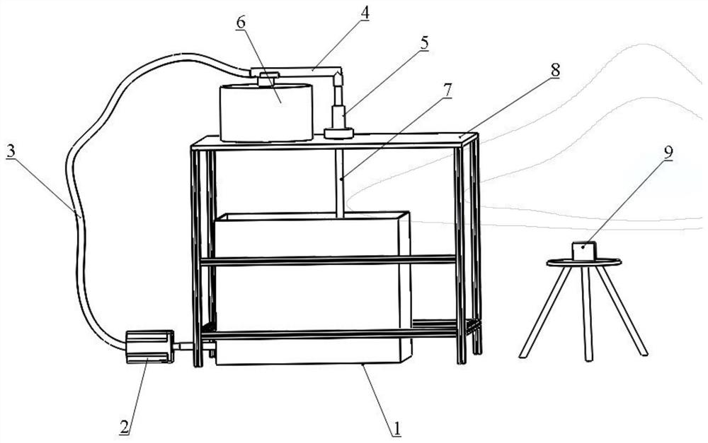
[0005] The purpose of the present invention is exactly in order to overcome the difficulty mentioned in the background technology, the experimental device that is used to measure the influence of flow velocity on the cantilever flow tube at present is relatively large, the equipment is heavy, the cost of the experimental equipment is high, and some parts inside are inconvenient to change. It is mostly used in fluid experiments, and there is no simple experimental device specially used for measuring cantilever flow pipes. In order to overcome this difficulty, the present invention designs a relatively simple experimental platform to measure the influence of flow velocity on vibration frequency. The present invention is the largest The advantage is that it is very convenient to change the experimental equipment if there is a problem. In addition, in order to ensure the accuracy of the experiment, some parts and fixtures are specially designed in the present invention to achieve the desired effect.

Method used


Image

  • Fluid-solid coupling experiment platform based on influence of flow velocity on cantilever fluid conveying pipe
  • Fluid-solid coupling experiment platform based on influence of flow velocity on cantilever fluid conveying pipe
  • Fluid-solid coupling experiment platform based on influence of flow velocity on cantilever fluid conveying pipe

Examples


Embodiment

[0017] Such as figure 1 As shown, the present invention discloses a fluid-solid coupling experimental platform specially used for experimentally measuring the influence of flow velocity on the cantilever delivery pipe, which mainly consists of a water tank (1), a water pump (2), an experimental platform (8), an excitation table ( 6), flange (5) and video camera (9) form.

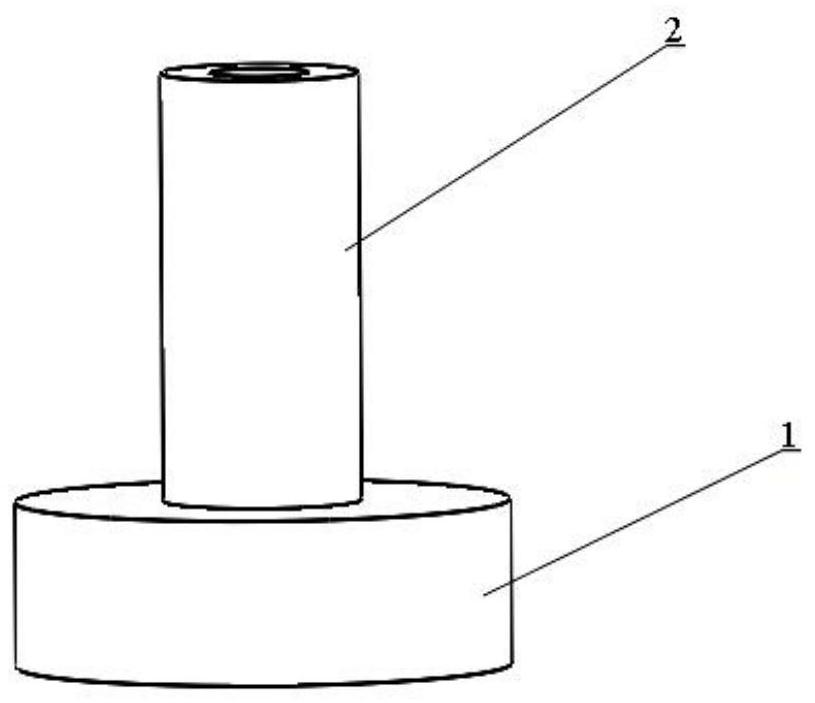
[0018] Such as Figure 2 to Figure 4 As shown, the important parts in the experiment include flanges, water tanks, fixtures, etc.

[0019] The specific experimental procedure for measuring the influence of the flow rate on the cantilever delivery tube is as follows:

[0020] For the first time, set the specific pressure value of the pulse water pump (2) to pump the water in the water tank (1) into the hose (3). These joints are used to connect hoses of different diameters. The hoses pass through the flanges. The flanges decouple the lateral vibration and axial vibration, and only retain the externally exc...


PUM


Abstract

The invention discloses a fluid-solid coupling experiment platform based on the influence of the flow velocity on a cantilever fluid conveying pipe. The experiment platform is composed of an experiment table, an excitation table, a pulse motor, a flange, a water tank, a camera and the like. The flange decouples transverse vibration displacement and axial vibration displacement and only retains axial vibration displacement, the water pump adopts a pulse water pump to ensure stable pulse flow velocity, the vibration excitation table and the hard tube are connected through a specially designed clamp, all required experiment devices are basic experiment devices used in experiments, in the way, what is guaranteed is that the experiment can meet the requirement for accurately measuring the influence of the flow velocity on the cantilever fluid conveying pipe, experiment equipment is not wasted, local materials are conveniently used, the experiment cost is reduced, the influence of the flow velocity on the vibration mode and the vibration frequency of the fluid conveying pipe is measured through a relatively simple experiment device, and the result accuracy is guaranteed.

Description

technical field [0001] The invention relates to the technical field of fluid-solid coupling flow delivery pipelines, in particular to the influence of experimentally measured flow velocity on the vibration of flow delivery pipelines. Background technique [0002] Fluid piping systems are widely used in power, petroleum, chemical industry, ships, aircraft and daily life. Fluid pipelines are used to transmit mass flow, momentum flow, and energy flow. At the same time, there are fluid pressure pulsations and structural vibrations of the pipe wall in the piping system, which may cause damage to the piping system in severe cases. There are many kinds of vibration waves in the fluid pipeline, and the vibration mechanism is very complicated. At the same time, vibration and accompanying noise also cause environmental pollution. The vibration of fluid pipeline is a typical fluid-solid coupling vibration. Fluid-structure coupled vibration is also called fluid-induced vibration. ...

Claims


Application Information

Patent Timeline
IPC IPC(8): G01M10/00
CPCG01M10/00
Inventor 张伟刘飞刘涛郑岩
Owner BEIJING UNIV OF TECH
Learn More