Contact Super Slippery Encoder
A contact and encoder technology, applied in the field of encoders, can solve the problems of low reliability and low life, and achieve the effects of high reliability, low friction and high resolution
- Summary
- Abstract
- Description
- Claims
- Application Information
AI Technical Summary
Problems solved by technology
Method used
Image
Examples
Embodiment 1
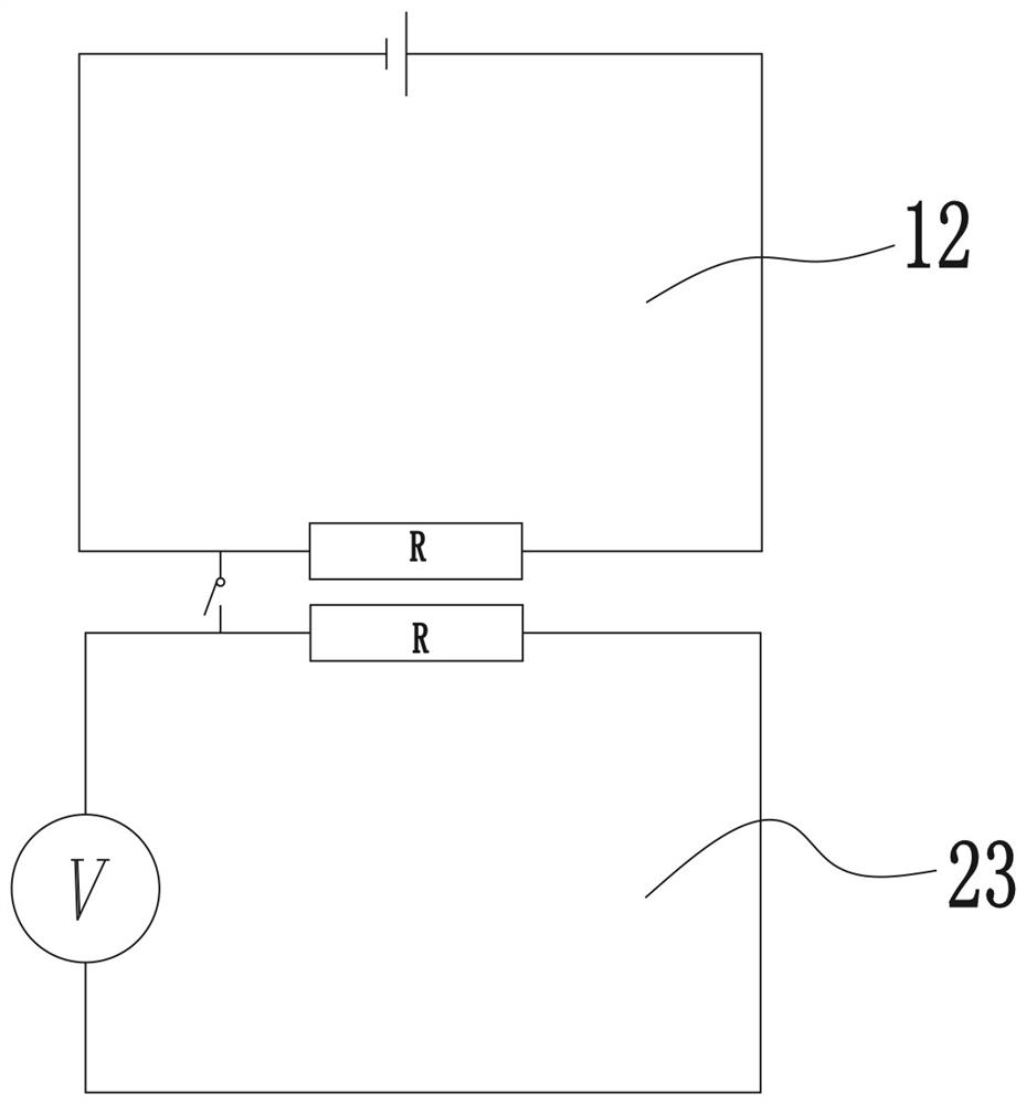
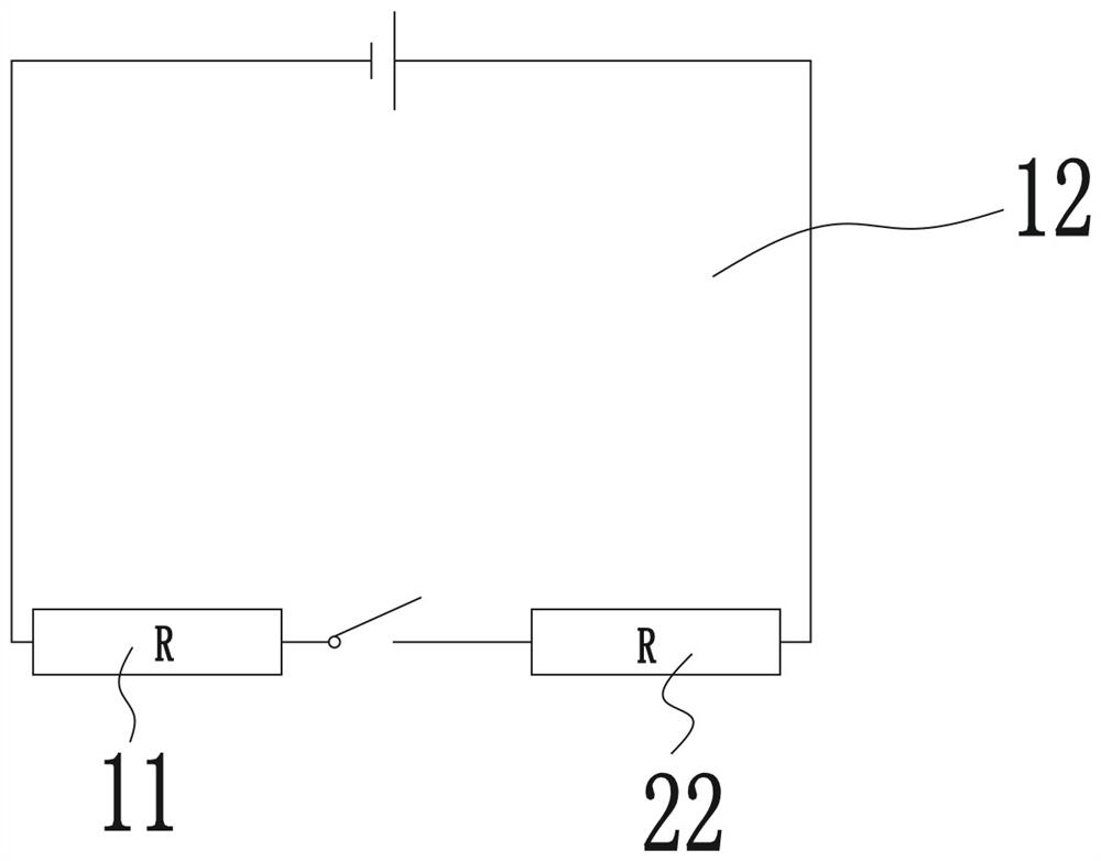
[0045] Please also refer to Figure 1 to Figure 3 , the contact type super-slip encoder provided by the present invention is now described. The contact type super-slip encoder includes a code disc assembly 1, a reading assembly 2 and a housing 3, the code disc assembly 1 is connected to an external fixed part, the reading assembly 2 is connected to an external rotating shaft 7, and the housing The body 3 is covered on the outside of the code wheel assembly 1 and the reading assembly 2, and the entire encoder is protected by the casing 3, and the casing 3 will not rub against the code wheel assembly 1 and the reading assembly 2 .
[0046] The housing 3 is fixedly connected to the code wheel assembly 1, a buffer layer 4 is placed between the housing 3 and the code wheel assembly 1, and one side of the buffer layer 4 is fixedly connected to the housing 3 , the other side is fixedly connected with the code wheel assembly 1; the buffer layer 4 can support the code wheel assembly ...
Embodiment approach
[0061] Further, see Figure 6 , as a specific embodiment of the contact type super-slip encoder provided by the present invention, the contact part 22 also includes a fixed head 221 and an elastic member 222, and the fixed head 221 connects with the rotating disk through the elastic member 222 21 is fixedly connected, the fixed head 221 has an arc-shaped surface towards the side of the super-slip code wheel 11, and the super-sliding piece 223 is fixed on the side of the arc-shaped surface closest to the super-slip code wheel 11, that is The super-sliding sheet 223 is located at the bottom of the entire fixed head 221, and the bottom of the fixed head 221 can only fix one super-sliding sheet 223, and can also fix a super-sliding sheet group, that is, a plurality of super-sliding sheets 223 are assembled to form The larger size Ultra Slider set.
[0062] Both sides of the super sliding sheet 223 are arc-shaped surfaces. At this time, when the entire super-sliding code disc 11 i...
Embodiment 2
[0071] refer to Figure 4 and Figure 5 , as another specific implementation of the contact-type super-slip encoder provided by the present invention, the difference between this embodiment and Embodiment 1 is that the housing 3 is fixedly connected to the reading assembly 2, and the housing 3 and the reading assembly 2 are provided with a buffer layer 4, one side of the buffer layer 4 is fixedly connected to the housing 3, and the other side is fixedly connected to the reading assembly 2; the buffer layer 4 can be used for reading Component 2 is used for support, and the contact and fit between code wheel component 1 and reading component 2 makes the positions of code wheel component 1 and reading component 2 inside the housing 3 relatively fixed, preventing code wheel component 1 from being separated when bumping .
[0072] The two side surfaces of described super slippery code wheel 11 all have described coding code track 111, and the quantity of described rotating disc 2...
PUM
 Abstract
Description
Claims
Application Information
 - R&D
- Intellectual Property
- Life Sciences
- Materials
- Tech Scout
- Unparalleled Data Quality
- Higher Quality Content
- 60% Fewer Hallucinations
Browse by: Latest US Patents, China's latest patents, Technical Efficacy Thesaurus, Application Domain, Technology Topic, Popular Technical Reports.
© 2025 PatSnap. All rights reserved.Legal|Privacy policy|Modern Slavery Act Transparency Statement|Sitemap|About US| Contact US: help@patsnap.com


