
Heat exchanger with spring rib structure

A technology of heat exchanger and rib structure, applied in heat exchange equipment, heat exchanger type, heat exchanger shell, etc., can solve the problems of short heat exchange time, low refrigerant flow rate, short heat exchange flow distance, etc., to achieve Reduce the impact of heat exchange efficiency, high product size accuracy, and solve the effect of short heat exchange stroke

Pending Publication Date: 2021-06-18
SHUNDE POLYTECHNIC
View PDF1 Cites 0 Cited by
  • Summary
  • Abstract
  • Description
  • Claims
  • Application Information

AI Technical Summary

Problems solved by technology

Obviously, this kind of heat exchanger in the form of a coil has a low flow rate of refrigerant on the effective heat exchange interface, so the flow of the refrigerant is laminar, and its heat exchange efficiency mechanism is higher than that of a heat exchanger in the form of a sleeve. Poor; the other side casing heat exchanger usually collects the refrigerant and the brine at both ends of the double-layer casing, but due to the limitation of the existing manufacturing technology, when the total length of the casing is long, It is difficult for the inner and outer sleeves to ensure the distance between the outer wall of the inner tube and the inner wall of the outer tube, especially during the coiling process. Therefore, it is difficult to make the existing double-layer sleeves longer and of any length. The common The casing spiral can only be coiled once or twice, because the length of the casing is limited, although the refrigerant flow rate in the interlayer between the outer wall of the inner tube and the inner wall of the outer tube can be fast and easily form turbulent flow, but the heat exchange flow distance Short, short heat exchange time leads to insufficient heat exchange, which makes the shortcomings of the heat exchanger in the form of casing more obvious

Method used


Image

  • Heat exchanger with spring rib structure
  • Heat exchanger with spring rib structure
  • Heat exchanger with spring rib structure

Examples


Embodiment Construction

[0027] The technical solution will be described in detail below in conjunction with specific embodiments.

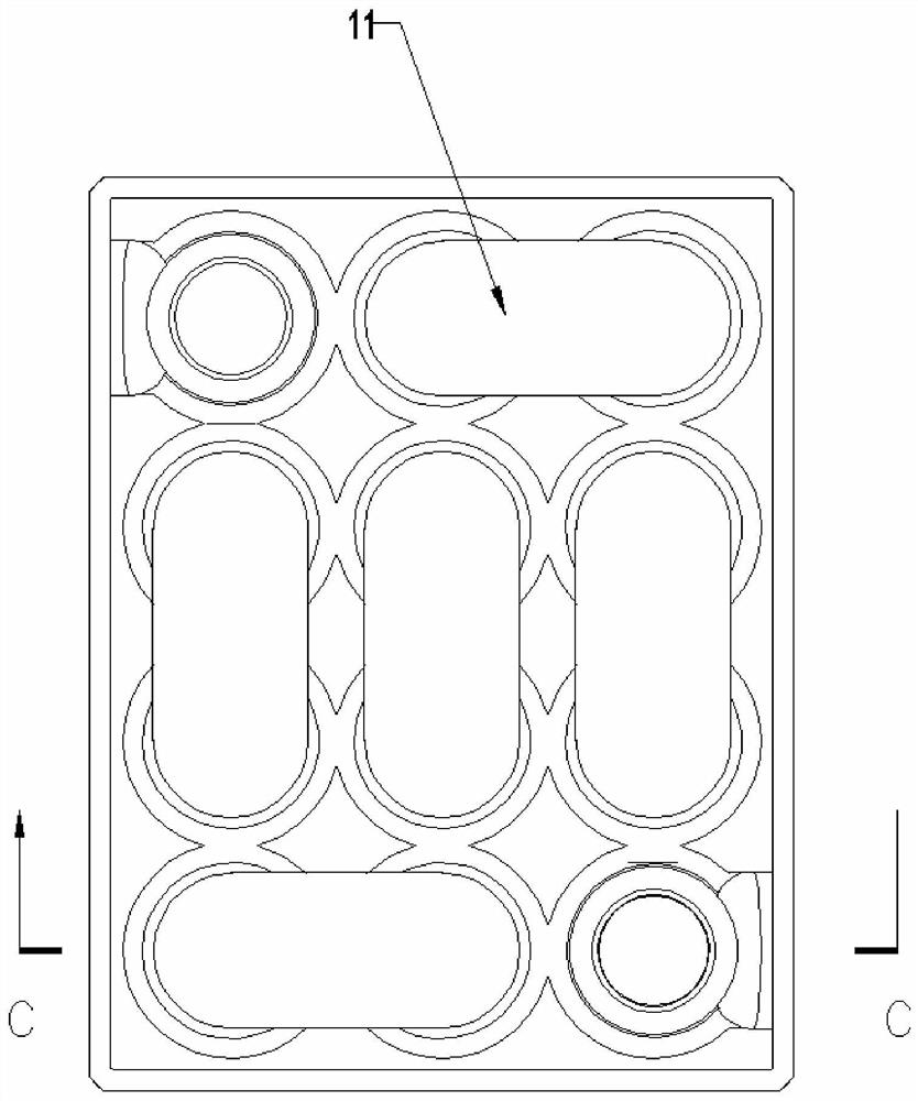
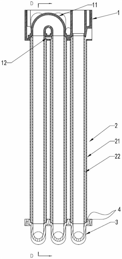
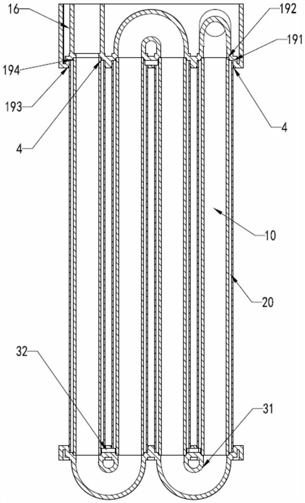
[0028] Such as Figure 1-10 As shown, the present invention discloses a heat exchanger with a spring rib structure, including a first end cover 1, a second end cover 3, a heat exchange sleeve 2, and a heat exchanger between the first and second end covers and the heat exchange sleeve. The two heat exchange channels formed are respectively the water channel 10 and the refrigerant channel 20 . The heat exchange sleeve 2 is composed of an inner tube 22 and an outer tube 21. As we know, in order to make the fluid heat exchange more fully, it can be realized by increasing the heat exchange area of ​​the two fluids and prolonging the heat exchange time between the two fluids. However, the traditional sleeve-type heat exchanger cannot extend the length of the heat exchange flow path due to the limitation of the length of the tube body. Although the screw-wound tube heat exchan...


PUM


Abstract

The invention discloses a heat exchanger of a spring rib structure. The heat exchanger comprises a first end cover and a second end cover and further comprises a heat exchange sleeve, the heat exchange sleeve comprises inner pipes and outer sleeves, the first end cover and the second end cover are provided with bottom plates, an elbow and a communicating groove are integrally formed in each bottom plate in a metal injection mode, the two ends of the elbows are opened in the bottom plates, the communicating grooves are formed in the plate wall portions, connected with the two opening portions of the elbows, of the bottom plates, the openings in the two ends of the elbows are connected with inner pipes of the two adjacent heat exchange sleeves, outer sleeve interlayers of the two adjacent heat exchange sleeves connected with the elbows communicate through the communicating grooves, and therefore, two independent heat exchange runners are formed between the first end cover and the heat exchange sleeves and between the second end cover and the heat exchange sleeves. According to the heat exchanger, the metal injection molding technology is applied, the reasonable and mature brazing welding technology is additionally adopted, integral forming of s bent pipe and a sleeve can be achieved in a simple and effective mode, a spring is installed in a pipe body, the screw pitch L of the spring meets the condition that L is smaller than 50*D, so that additional heat resistance is reduced, and the heat exchange effect is better.

Description

technical field [0001] The invention relates to the technical field of heat exchange equipment, more specifically, to a heat exchanger with a spring rib structure. Background technique [0002] The heat exchanger of the existing heat pump water heater mainly includes a shell, an inner cylinder and a coil. The coil is spirally coiled in the annular space between the shell and the inner cylinder. The refrigerant inlet is located on the upper part of the side wall of the shell. After entering the annular tube space between the shell and the inner tube from the side wall of the gas phase, the refrigerant in the gas phase descends along the annular tube space, contacts the outer surface of the coil, exchanges heat with the water in the coil, and gradually condenses , The refrigerant soaks the coil in the lower part of the annular tube space, and after reaching the bottom, enters the inner tube through the four holes at the bottom of the inner tube, rises from the inner tube, and ...

Claims


Application Information

Patent Timeline
Patent Type & Authority Applications(China)
IPC IPC(8): F28D7/10F28F9/26F28F9/02F28F1/08F28F21/08B22F3/22
CPCB22F3/22F28D7/106F28F1/08F28F9/0229F28F9/26F28F21/08
Inventor 余华明畅国帏李东洺
Owner SHUNDE POLYTECHNIC
Learn More