
Water plant sludge dewatering automatic control system

An automatic control system, sludge dewatering technology, applied in the general control system, control/regulation system, water/sludge/sewage treatment, etc., can solve the inconvenience of operation, low control efficiency and operation efficiency, control effect and function Unevenness and other problems, to achieve high-efficiency control, ensure operating efficiency, and save time and cost

Pending Publication Date: 2021-06-18
SHANGHAI YUANDONG SCI & TECH
View PDF5 Cites 3 Cited by
  • Summary
  • Abstract
  • Description
  • Claims
  • Application Information

AI Technical Summary

Problems solved by technology

[0002] As an urban tap water purification treatment plant, a waterworks will produce a large amount of sludge and wastewater by-products during its raw water purification process. With the increasingly strict trend of the country's environmental protection policies, the centralized treatment of sludge and wastewater from waterworks prevents secondary Pollution has become a necessary process link in the water production process of water plants, and the automatic control system supporting sludge treatment has also been developed. However, the control methods of sludge dewatering are different at present, and the control effects and functions are also uneven.
Most of the control methods have to be interrupted after the failure of the equipment, such as the failure of the power source such as the water pump and the motor, and the maintenance personnel need to repair it before continuing to process. It is inconvenient to operate and does not have timely alarm operation. , leading to inefficiencies in control and operation

Method used


Image

  • Water plant sludge dewatering automatic control system
  • Water plant sludge dewatering automatic control system
  • Water plant sludge dewatering automatic control system

Examples


Embodiment

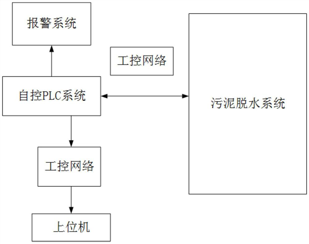
[0033] The invention relates to an automatic control system for sludge dehydration in a waterworks, comprising an automatic control PLC system, a sludge dewatering system, an industrial control network, a host computer and an alarm system.

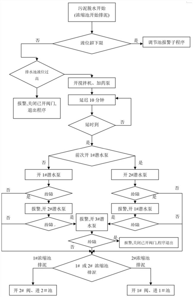
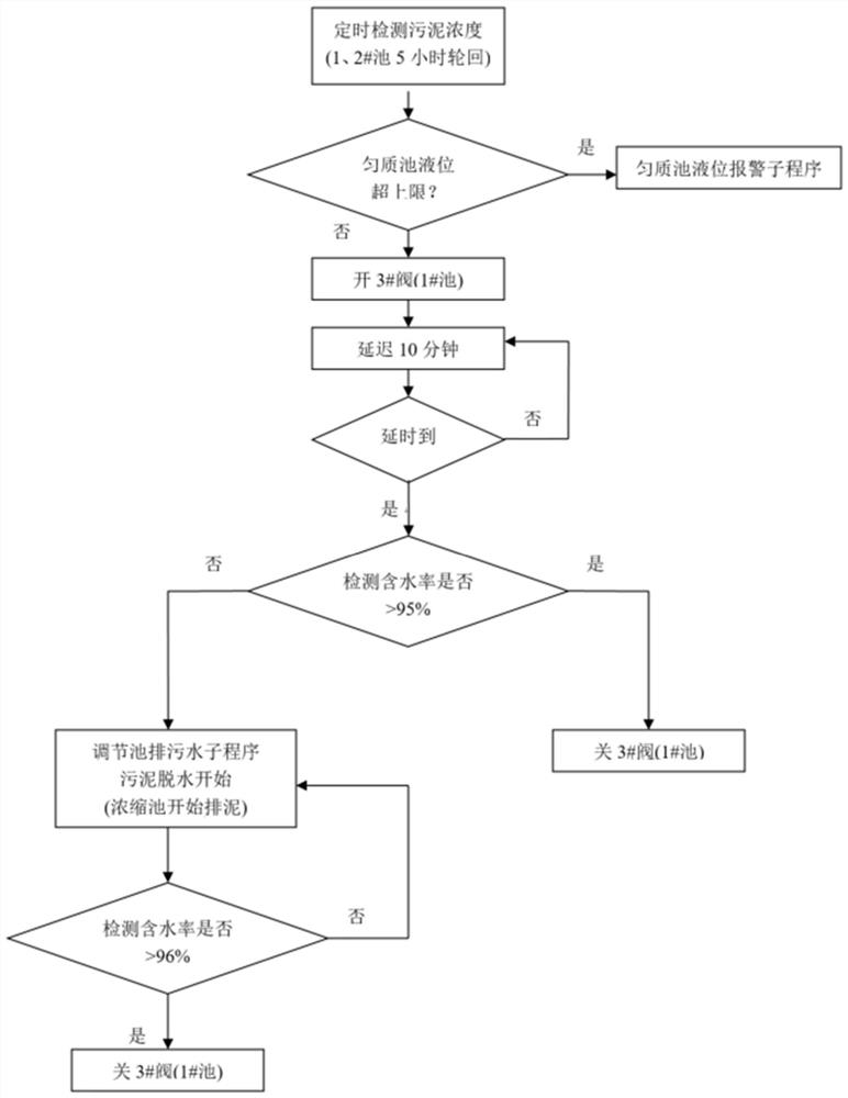
[0034] The dehydration process is the core process of the whole sludge dewatering treatment. The sludge dewatering system includes a regulating tank, a thickening tank, a thickening machine, a filter press equipment group and a liquid distribution system. The sewage in the regulating tank is pumped into the thickening tank through a submersible pump. There is a concentration meter for measuring the concentration of sludge. The filter press equipment group separates the mud and water in the sludge under the action of the liquid distribution system, and the dry mud is produced through the extrusion of the filter cloth. The filter press equipment group includes sewage. Mud pumps, flushing pumps, submersible pumps, coagulators, filter presses,...


PUM


Abstract

The invention relates to a water plant sludge dewatering automatic control system, which comprises a self-control PLC system, a sludge dewatering system, an industrial control network and an alarm system, wherein theself-control PLC system is usedfor executing state signal acquisition and corresponding switch control of field equipment included in a sludge dewatering system, processing the acquired state signals, sending the processed state signals to an upper computer, and executing logic judgment and processing according to the acquired state signals; the sludge dewatering system is used for executing the control instruction sent by the automatic control PLC system and integrally completing the processes of sludge flocculation, concentration and dewatering; the industrial control network provides data transmission channels between the self-control PLC system and the upper computer, between the self-control PLC system and the alarm system and between the self-control PLC system and the sludge dewatering system, and the upper computer obtains a state signal sent by the self-control PLC system and obtains the running state of the sludge dewatering machine; and the alarm system is in wireless connection with the self-control PLC system and gives an alarm for the failure problem, judged by the self-control PLC system, of the sludge dewatering system. Compared with the prior art, the system has the advantages of high operation efficiency, cost saving and the like.

Description

technical field [0001] The invention relates to the technical field of sludge treatment, in particular to an automatic control system for sludge dewatering in waterworks. Background technique [0002] As an urban tap water purification treatment plant, a waterworks will produce a large amount of sludge and wastewater by-products during its raw water purification process. With the increasingly strict trend of the country's environmental protection policies, the centralized treatment of sludge and wastewater from waterworks to prevent secondary Pollution has become a necessary process link in the water production process of water plants, and the automatic control system supporting sludge treatment has also been developed. However, the control methods of sludge dewatering are different at present, and the control effects and functions are also uneven. Most of the control methods have to be interrupted after the failure of the equipment, such as the failure of the power source s...

Claims


Application Information

Patent Timeline
Patent Type & Authority Applications(China)
IPC IPC(8): C02F11/121C02F11/14C02F11/12C02F11/122G05B19/05
CPCC02F11/121C02F11/14C02F11/12C02F11/122G05B19/054C02F2209/005C02F2201/002C02F2201/004C02F2201/005C02F2209/008C02F2303/14
Inventor 胡介民胡嘉宁
Owner SHANGHAI YUANDONG SCI & TECH
Learn More