Spray production line and spray cleaning method

A technology for production lines and cleaning devices, applied in cleaning methods and utensils, cleaning methods using liquids, chemical instruments and methods, etc., can solve the problems of poor cleaning effect and low cleaning efficiency of large valves, and achieve convenient transportation and improved effect. Effect

Active Publication Date: 2016-03-30
王良源
View PDF6 Cites 4 Cited by
  • Summary
  • Abstract
  • Description
  • Claims
  • Application Information

AI Technical Summary

Problems solved by technology

[0004] Therefore, the technical problem to be solved by the present invention lies in the problems of poor cleaning effect and low cleaning efficiency when cleaning large valves in the prior art, thereby proposing a spray production line suitable for large valves with good cleaning effect and high cleaning efficiency and Spray cleaning method

Method used


Image

  • Spray production line and spray cleaning method
  • Spray production line and spray cleaning method
  • Spray production line and spray cleaning method

Examples


Embodiment 1

[0034] This embodiment provides a spray production line for large valves, including:

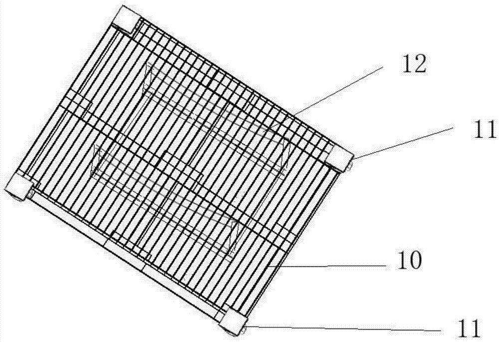
[0035] carrying device, such as figure 1 As shown, it includes a hollow base 10, a wheel 11 arranged at the bottom of the base, a fixing frame 12 arranged on the base, and the fixing frame 12 has two arc-shaped plates for matching with the valve body shape of the valve. Coordination; the hollow base 10 is to facilitate the cleaning liquid to pass through the hollow bottom when it is sprayed upwards, the wheels 11 are set to facilitate the movement of the carrying device, and the fixing frame is to facilitate the fixing and placement of the valve;

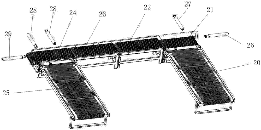
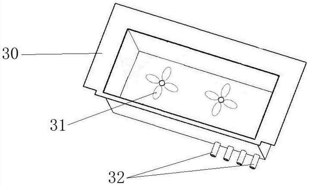
[0036] The cleaning device sequentially includes a first immersion device for rinsing the valve with cleaning liquid, a spray rinsing device for rinsing the valve in six mutually perpendicular directions with cleaning liquid, and a cleaning device for rinsing the valve with clean water. The second rinsing device for rinsing the valve, and the air...

Embodiment 2

[0068] This embodiment provides a large-scale valve cleaning method, adopting the large-scale valve production line described in Embodiment 1, comprising the following steps,

[0069] S1: Rinse the valve with cleaning solution. In this step, use the paddle to stir the cleaning solution. The rotation speed of the paddle is 100-150r / min, such as 100r / min, 120r / min, 150r / min, etc. The blade rotation time is 40-50min, such as 40min, 45min, 50min, etc. After using the paddle to stir the cleaning liquid, it also includes the process of cleaning the valve with ultrasonic waves. The ultrasonic frequency is 28kHz-35kHz, such as 28kHz, 30kHz, 35kHz, etc. , the power is 2-2.5w / cm 2 , such as 2w / cm 2 , 2.2w / cm 2 , 2.5w / cm 2 etc., ultrasonic cleaning time is 20-40min, such as 20min, 30min, 40min, etc.;

[0070] S2: Use cleaning liquid to flush the valve in six mutually perpendicular directions. In this step, the spray speed of cleaning liquid is 30-40m / s, such as 30m / s, 35m / s, 40m / s, e...


PUM


Abstract

The invention discloses a spray production line and a spray cleaning method. Through a spray washing device, washing in six mutually perpendicular directions can be carried out on a valve with a cleaning fluid; particularly, the bottom of a bearing device is in a hollow state, and gaps between adjacent toothed chains form water spray gaps, so that the cleaning fluid can be sprayed from the bottom up to carry out spray washing on the bottom of the valve, and the technical defect in the prior art that the bottom of the valve can not be washed is overcome. Water spray pipes of a bottom cleaning device, an upper cleaning device, a left cleaning device and a right cleaning device form an annular frame or a rectangular frame, and a plurality of nozzles are distributed in the annular frame or the rectangular frame, so that the spray washing in six mutually perpendicular directions can be carried out on the valve, the all-dimensional washing on the valve is realized, and the spray washing effect is improved.

Description

technical field [0001] The invention relates to a spray production line and a spray cleaning method for large valves, belonging to the technical field of valve manufacturing equipment. Background technique [0002] On natural gas, oil and other energy transmission pipelines, the diameter of the pipeline is usually more than 500mm, and in order to make the natural gas and oil flow smoothly in the pipeline, it is necessary to exert a large pressure in the pipeline, which makes the large valves installed on the energy pipeline The size is huge, the quality is heavy, and the quality reaches more than 20kg, and some even exceed 50kg. [0003] During the manufacturing process of the above-mentioned large valves and after the assembly is completed, the valves need to be cleaned. For example, when the valve core is installed in the valve cavity, it is necessary to clean the valve core and the valve cavity to ensure the tightness after assembly. After the valve is assembled, it mus...

Claims


Application Information

Patent Timeline
Patent Type & Authority Applications(China)
IPC IPC(8): B08B3/02B08B3/04
CPCB08B3/022B08B3/041
Inventor 王良源
Owner 王良源
Why Eureka
Try Eureka