
Charging circuit and electronic equipment

A charging circuit and electronic equipment technology, applied in battery circuit devices, charging/discharging current/voltage regulation, circuits, etc., to achieve the effect of reducing thermal stack design, avoiding heating state, and reducing thermal power consumption

Pending Publication Date: 2021-06-15
BEIJING XIAOMI MOBILE SOFTWARE CO LTD
View PDF4 Cites 0 Cited by
  • Summary
  • Abstract
  • Description
  • Claims
  • Application Information

AI Technical Summary

Problems solved by technology

However, increasing the number of batteries brings new challenges to battery charging methods and charging efficiency

Method used


Image

  • Charging circuit and electronic equipment
  • Charging circuit and electronic equipment
  • Charging circuit and electronic equipment

Examples


Embodiment Construction

[0035] Reference will now be made in detail to the exemplary embodiments, examples of which are illustrated in the accompanying drawings. When the following description refers to the accompanying drawings, the same numerals in different drawings refer to the same or similar elements unless otherwise indicated. The implementations described in the following exemplary examples do not represent all implementations consistent with the present disclosure. Rather, they are merely examples of apparatuses and methods consistent with aspects of the present disclosure as recited in the appended claims.

[0036] The terminology used in the present disclosure is for the purpose of describing particular embodiments only, and is not intended to limit the present disclosure. As used in this disclosure and the appended claims, the singular forms "a", "the", and "the" are intended to include the plural forms as well, unless the context clearly dictates otherwise. It should also be understood...


PUM


Abstract

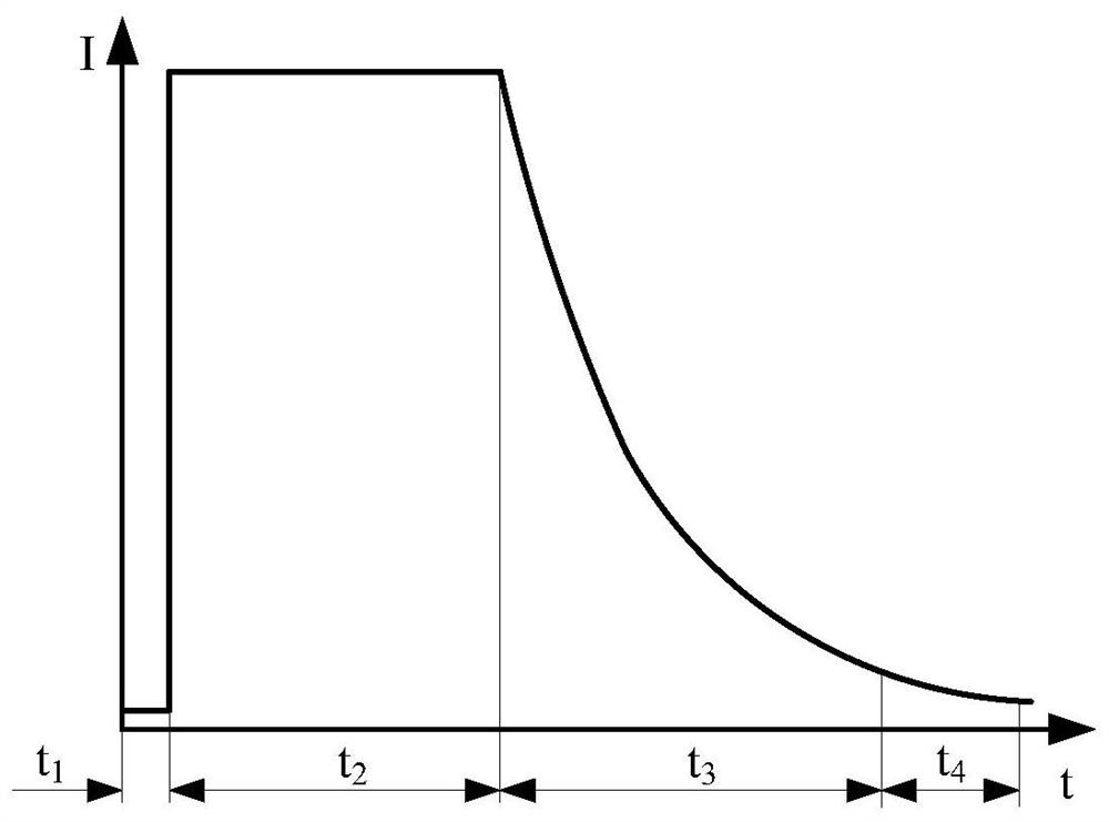
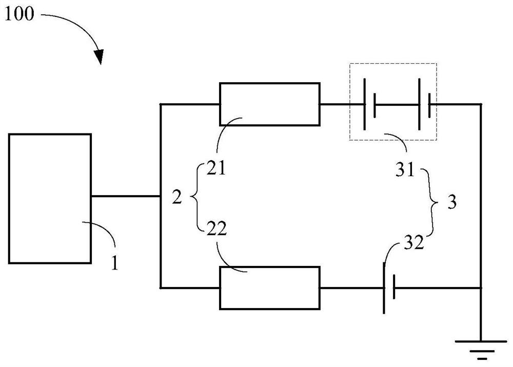
The invention relates to a charging circuit and electronic equipment. The charging circuit comprises an interface module, a plurality of charging management modules, and a plurality of battery packs; the plurality of charging management modules are connected to the interface module in parallel; each battery pack comprises a battery or a plurality of batteries connected in series; the plurality of battery packs being connected in series with the plurality of charging management modules in a one-to-one manner; the plurality of battery packs are connected in parallel; and the plurality of charging management modules are electrically connected with one another, so that charging current input to each battery pack is adjusted through signal interaction among the plurality of charging management modules, the time period of the maximum charging current corresponding to each battery pack is different from the time periods of the maximum charging current corresponding to other battery packs.

Description

technical field [0001] The present disclosure relates to the technical field of terminals, and in particular to a charging circuit and electronic equipment. Background technique [0002] Currently, as the functions of smart terminals become more and more powerful, their power consumption will also increase accordingly. Therefore, in order to meet the power consumption of the smart terminal and prolong the battery life of the smart terminal, some smart terminals have begun to be equipped with multiple batteries to increase the battery capacity. However, increasing the number of batteries brings new challenges to the battery charging method and charging efficiency. Contents of the invention [0003] The present disclosure provides a charging circuit and electronic equipment to solve the deficiencies in the related art. [0004] According to a first aspect of an embodiment of the present disclosure, there is provided a charging circuit, including: [0005] an interface mod...

Claims


Application Information

Patent Timeline
IPC IPC(8): H02J7/00
CPCH02J7/0013H02J7/007H02J7/00309H02J7/00712H02J7/005H02J7/342H02J7/0025H01M50/20H01M10/425H01M10/441
Inventor 孙长宇
Owner BEIJING XIAOMI MOBILE SOFTWARE CO LTD
Learn More