
Combined transformer load switch and plug-in fuse interlocking method and device

A combined transformer and load switch technology, applied in inductance/transformer/magnet manufacturing, electrical switches, electrical component structure associations, etc., can solve problems such as power grid safety accidents, misoperation of power grids, safety accidents, etc., to prevent power grid safety accidents. Occur, prevent misoperation, and prevent the effect of preventing the flip of the protective plate

Pending Publication Date: 2021-06-11
GUANGDONG BAICHANG ELECTRIC POWER EQUIP CO LTD
View PDF0 Cites 0 Cited by
  • Summary
  • Abstract
  • Description
  • Claims
  • Application Information

AI Technical Summary

Problems solved by technology

[0004] One of the purposes of the present invention is to provide a combined transformer load switch and plug-in The interlocking method of type fuses, which can prevent plug-in fuses from being pulled out under misoperation and prevent power grid safety accidents, etc.
[0005] The second purpose of the present invention is to provide a combined transformer load switch with plug-in Type fuse interlocking device, which has outstanding substantive features and significant technological progress, such as simple structure, can prevent plug-in fuses from being pulled out under misoperation, and prevent power grid safety accidents.

Method used


Image

  • Combined transformer load switch and plug-in fuse interlocking method and device
  • Combined transformer load switch and plug-in fuse interlocking method and device
  • Combined transformer load switch and plug-in fuse interlocking method and device

Examples


specific Embodiment 1

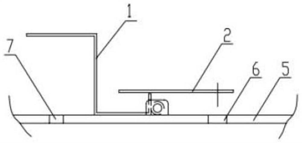
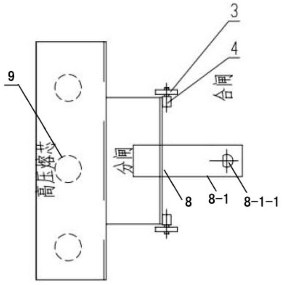
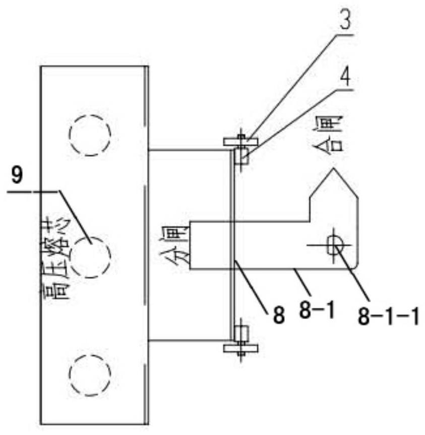
[0029] refer to Figure 1 to Figure 3 , the combined transformer load switch and plug-in fuse interlocking device involved in this embodiment has structural features: including a protective cover 1, a clamping plate 2, a fixing plate 3, a protective cover rotating shaft 4, a fuel tank cover plate 5, and a load switch Shaft mounting hole 6 and plug-in fuse holder mounting hole 7, protective cover rotating shaft 4 is welded on protective cover 1, fixed plate 3 is welded on fuel tank cover 5, clamping plate 2 is fixed on load switch rotating shaft mounting hole 6, and the load The switch shaft installation hole 6 and the plug-in fuse holder installation hole 7 are arranged on the same surface of the fuel tank cover 5, the load switch shaft installation hole 6 and the plug-in fuse holder installation hole 7 are arranged on the fuel tank cover 5, and the protective cover 1 is fixed on the fuel tank cover 5 to protect the plug-in fuse, and the clip 2 is used to protect the load swit...

specific Embodiment 2

[0041] refer to Figure 4 to Figure 6 , Figure 8 The characteristics of this embodiment are: the load switch of the combined transformer is a four-position load switch structure, the protective cover shaft 4 is welded on the protective cover 1, the fixing plate 3 is welded on the fuel tank cover plate 5, and the clamping plate 2 is fixed on the load On the installation hole 6 of the switch shaft, the insulating operating rod is used for the live closing and opening operation of the load switch. The operating rod hooks the operating hole of the load switch handle and rotates clockwise or counterclockwise to the required position. When the operating lever is turned to the card board to indicate that the power supply Ⅰ and Ⅱ are connected, and the transformer is disconnected, it means that the high-voltage fuse is powered off, and the protective cover can be opened to pull out the plug-in fuse holder to replace the high-voltage fuse.

[0042] The four-position load switch descr...


PUM


Abstract

The invention relates to a combined transformer load switch and plug-in fuse interlocking method and device. The method is characterized in that: an interlocking device is arranged, a protective cover rotating shaft of the interlocking device is welded to a protective cover, a fixing plate is welded to an oil tank cover plate, and a clamping plate is fixed to a rotating shaft mounting hole of a load switch; when an insulation operating rod hooks a handle operating hole of the load switch and rotates clockwise to a switching-on position, a transformer is in a switching-on state, the clamping plate clamps the protective cover, the protective cover cannot turn over, and the load switch and a plug-in fuse are in a hidden state; when the protective cover rotates anticlockwise to an opening position, the transformer is in a disconnected state, the clamping plate loosens the protective cover, the protective cover can be turned over, and the load switch and the plug-in fuse are in an open state; a rotation angle of the insulating operating rod is limited by the clamping plate, and the high-voltage fuse is controlled to be powered on or powered off; and in a power-off state, the clamping plate loosens the protective cover and the protective cover can be turned over. The method and the device have the advantages of preventing the protection plate from turning over, preventing misoperation, preventing power grid safety accidents and the like.

Description

technical field [0001] The invention relates to a method and device for interlocking a combined transformer load switch and a plug-in fuse, and belongs to the technical field of power supply and distribution equipment in a power system. Background technique [0002] The combined transformer is usually called "American box transformer". Its structural feature is that the transformer body, high voltage load switch, plug-in fuse and high and low voltage connections are arranged in a closed oil tank. In the prior art, the general combined transformer load switch and the plug-in fuse holder are not related to each other, and there is no interlock function, and only a warning sign can be used to remind customers to strictly prohibit live operation when live. Since the high-voltage load switch and plug-in fuse are assembled on the back of the box cover, and there is no operation protection structure, the high-voltage load switch and plug-in fuse are exposed on the working surface, ...

Claims


Application Information

Patent Timeline
IPC IPC(8): H01F41/00H01F27/40H01H9/20
CPCH01F27/40H01F41/00H01H9/20
Inventor 刘建南卢东杰
Owner GUANGDONG BAICHANG ELECTRIC POWER EQUIP CO LTD
Learn More