Method for identifying natural gas hydrate by using longitudinal and transverse wave velocity increment cross plot
A technology of velocity increment and longitudinal wave velocity, which is applied in seismology, measurement devices, geophysical measurements, etc. in areas covered by water, can solve problems such as elevation identification and low reliability of natural gas hydrate, and achieve Credibility-enhancing effects
- Summary
- Abstract
- Description
- Claims
- Application Information
AI Technical Summary
Problems solved by technology
Method used
Image
Examples
Embodiment 1
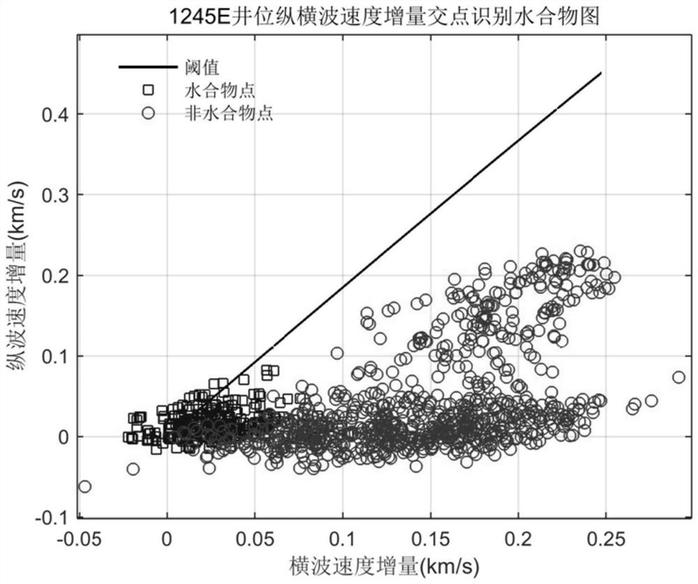
[0065] The 204 voyage of Ocean Drilling drilled at the 1245E well site of Oregon Hydrate Ridge, and found the existence of gas hydrate. In this example, the P- and S-wave velocity logging data known at the 1245E well location are used to calculate the P- and S-wave velocity of the water-saturated formation at the well location, and the P- and S-wave velocity increment is calculated. The threshold curve is calculated according to the determined formation parameters, and the judgment is made. Whether the formation contains gas hydrate or not is compared with the actual data of the gas hydrate position.
[0066] The method for identifying gas hydrate and estimating the range of gas hydrate saturation by using the intersection diagram of formation compressional and shear wave velocity increments includes the following steps:
[0067] (1) P-wave velocity (V p0 , V s0 ), referred to as the calculated velocity, and the measured velocity of formation compressional and shear waves (V...
Embodiment 2
[0077] The 204 voyage of Ocean Drilling drilled at well position 1247B of the Oregon Hydrate Ridge, and found the existence of gas hydrate. In this example, using the known P-wave velocity logging data at the 1247B well location, the P- and S-wave velocity of the gas-bearing water-saturated formation at this well location is calculated, the P- and S-wave velocity increment is calculated, and the threshold curve is calculated according to the determined formation parameters. , to determine whether the formation contains gas hydrate, and compare it with the actual data of the gas hydrate position.
[0078] The method for identifying gas hydrate and estimating the range of gas hydrate saturation by using the intersection diagram of formation compressional and shear wave velocity increments includes the following steps:
[0079] (1) P-wave velocity (V p0 , V s0 ) and the measured formation P-s wave velocity (V p , V s ) curves are shown in Figure 4(a) and Figure 4(b);
[0080...
Embodiment 3
[0089] The 204 voyage of Ocean Drilling drilled at the 1250F well site of Oregon Hydrate Ridge, and found the existence of gas hydrate. In this example, using the known P-wave velocity logging data at the 1250F well location, the P- and S-wave velocity of the gas-bearing water-saturated formation at the well location is calculated, the P- and S-wave velocity increment is calculated, and the threshold curve is calculated according to the determined formation parameters. , to determine whether the formation contains gas hydrate, and compare it with the actual data of the gas hydrate position.
[0090] The method for identifying gas hydrate and estimating the range of gas hydrate saturation by using the intersection diagram of formation compressional and shear wave velocity increments includes the following steps:
[0091] (1) P-wave velocity (V p0 , V s0 ) and the measured formation P-s wave velocity (V p , V s ) curves are shown in Figure 7(a) and Figure 7(b);
[0092] (2)...
PUM
 Abstract
Description
Claims
Application Information
 - R&D
- Intellectual Property
- Life Sciences
- Materials
- Tech Scout
- Unparalleled Data Quality
- Higher Quality Content
- 60% Fewer Hallucinations
Browse by: Latest US Patents, China's latest patents, Technical Efficacy Thesaurus, Application Domain, Technology Topic, Popular Technical Reports.
© 2025 PatSnap. All rights reserved.Legal|Privacy policy|Modern Slavery Act Transparency Statement|Sitemap|About US| Contact US: help@patsnap.com


