
Constant-temperature transport vehicle for industrial chemicals

A technology of chemicals and transport vehicles, which is applied in the direction of article transport vehicles, vehicles used for freight transportation, transport objects, etc., can solve problems such as high temperature and industrial chemical reactions, and achieve the effect of preventing temperature rise and conduction

Inactive Publication Date: 2021-06-11
李旭
View PDF0 Cites 0 Cited by
  • Summary
  • Abstract
  • Description
  • Claims
  • Application Information

AI Technical Summary

Problems solved by technology

[0006] In order to solve the above-mentioned technology, when the industrial chemical transport vehicle is placed outdoors for a long time, and the interior is equipped with industrial chemicals, it is easier to make the internal temperature of the top of the tank higher than that of the bottom, resulting in the reaction of the industrial chemicals in the tank.

Method used


Image

  • Constant-temperature transport vehicle for industrial chemicals
  • Constant-temperature transport vehicle for industrial chemicals
  • Constant-temperature transport vehicle for industrial chemicals

Examples


Embodiment 1

[0032] as attached figure 1 To attach Figure 6 Shown:

[0033] The present invention provides a constant temperature transport vehicle for industrial chemicals, the structure of which includes a bottom bracket 11, wheels 22, side fixing rods 33, a tank body 44, and a headstock 55. The bottom bracket 11 is installed between the wheels 22, The top of the bottom bracket 11 is fixed to the bottom of the tank body 44 , the side fixing rod 33 is welded to the outer surface of the tank body 44 , and the tank body 44 is connected to the headstock 55 .

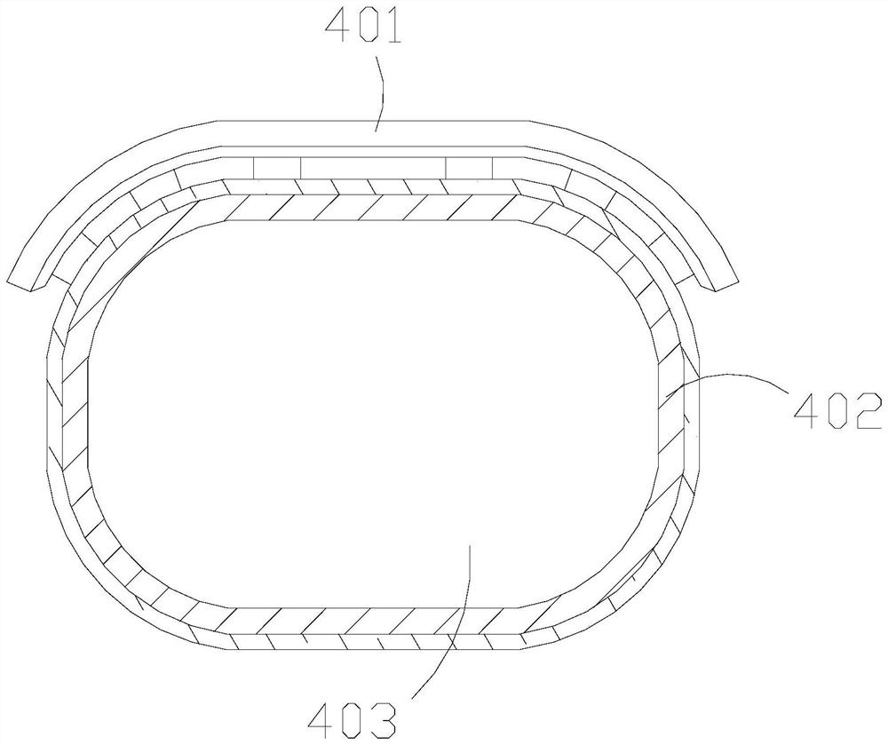
[0034] The tank body 44 includes a cover plate 401 , a sealed tank 402 , and a built-in compartment 403 , the built-in compartment 403 and the sealed tank 402 are of an integrated structure, and a cover plate 401 is installed on the top of the sealed tank 402 .

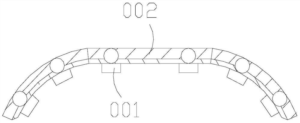
[0035] Wherein, the cover plate 401 includes a spacer 001 and a heat insulation plate 002, the spacer 001 is fixed on the lower end of the heat insulation plate 002, there ...

Embodiment 2

[0042] as attached Figure 7 To attach Figure 9 Shown:

[0043] Wherein, the spacer 001 includes a top spacer g01, a heat insulator g02, and a thermal insulation block g03, the heat separation block g03 and the heat insulation body g02 are an integrated structure, and the top spacer g01 is fixed on the heat insulation body The lower surface of g02, the heat sub-block g03 is an arc-shaped structure, the heat sub-block g03 can collect its heat to a certain extent through its own shape, and the top spacer g01 further separates the temperature from the tank body position between.

[0044] Wherein, the top spacer g01 includes a point contact ball x11, a surface extension block x12, a guide block x13, and a spacer block x14. The surface extension block x12 is attached to the outer surface of the point contact ball x11. The surface extension block x12 is about Both sides are connected with the guide block x13, the outer side of the guide block x13 is attached to the spacer block x1...


PUM


Abstract

The invention discloses a constant-temperature transport vehicle for industrial chemicals. The constant-temperature transport vehicle structurally comprises a bottom supporting frame, wheels, side fixing rods, a tank body and a vehicle head, wherein the bottom supporting frame is installed between the wheels, the top of the bottom supporting frame is fixed to the bottom of the tank body, the side fixing rods are welded to the outer surface of the tank body, and the tank body is connected with the vehicle head; the partition block connected with the heat insulation plate can be supported between the heat insulation plate and the sealing tank, heat is guided and dissipated towards a certain radian, the heat conduction block can disperse and evenly divide the heat when the top is exposed to the sun through the heat borne by the outer protection ball and evenly divided by the partition strip, the heat cannot be directly conducted to the tank body, some residual heat of the heat insulation plate can be conducted to the heat insulation body and the heat distribution block, the contact point of the point contact ball and the tank body is shrunk, the spacer block is made of a non-heat-conducting material, the uniformizing block strip is located in the uniformizing block, the temperature can be dispersed layer by layer again, a small contact surface can be formed at the supporting part between the heat insulation plate and the tank body, and rising conduction of the temperature can be prevented.

Description

technical field [0001] The invention belongs to the field of industrial chemistry, and more specifically relates to a constant temperature transport vehicle for industrial chemicals. Background technique [0002] Industrial chemicals are loaded into filling transport vehicles for mobile closed transportation, and their industrial chemicals are connected to the tank through pipelines, so that they can quickly transfer the location of industrial chemicals. [0003] Based on the inventor's discovery above, the existing industrial chemical constant temperature transport vehicles mainly have the following deficiencies, such as: [0004] When the industrial chemical transport vehicle is exposed to the outdoors for a long time, and the interior is equipped with industrial chemicals, it is easy to make the internal temperature of the top of the tank higher than that of the bottom, which will cause the industrial chemicals in the tank to react. [0005] Therefore need to propose a k...

Claims


Application Information

Patent Timeline
Patent Type & Authority Applications(China)
IPC IPC(8): B60P3/22
CPCB60P3/2205B60P3/224
Inventor 李旭
Owner 李旭
Learn More