
An inflatable shaft repair device

An inflatable shaft, coaxial technology, applied in workpiece clamping devices, manufacturing tools, hand-held tools, etc., can solve problems such as difficulty in separating the inflatable end from the inflatable shaft

Active Publication Date: 2022-07-15
上海贝承机械制造有限公司
View PDF6 Cites 0 Cited by
  • Summary
  • Abstract
  • Description
  • Claims
  • Application Information

AI Technical Summary

Problems solved by technology

[0004] In view of the above-mentioned related technologies, in the process of drawing the inflatable end of the air rod, through the abutment of the threaded compression rod, the inventor believes that the inflatable shaft is also pulled, and the inflatable end and the inflatable The defect that the shaft is difficult to disengage

Method used


Image

  • An inflatable shaft repair device
  • An inflatable shaft repair device
  • An inflatable shaft repair device

Examples


Embodiment Construction

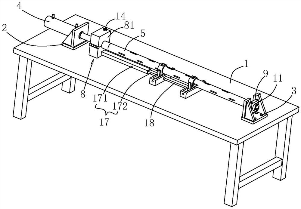
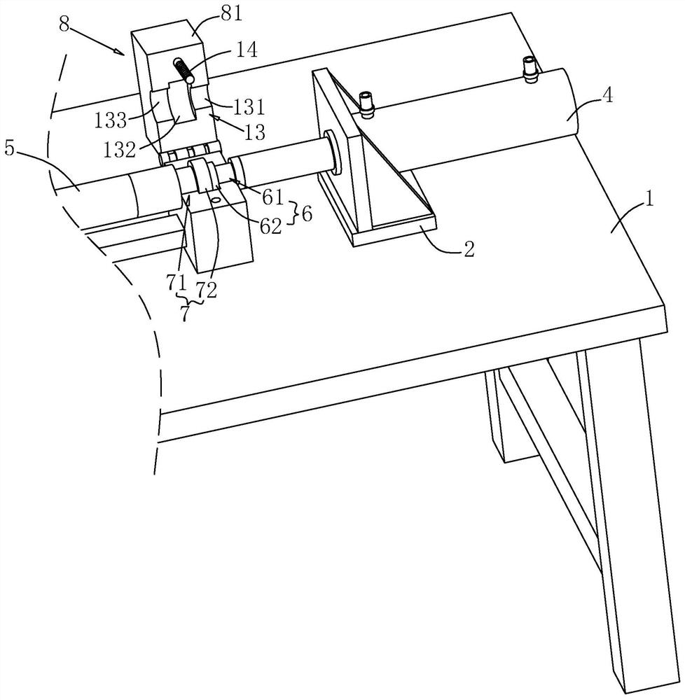
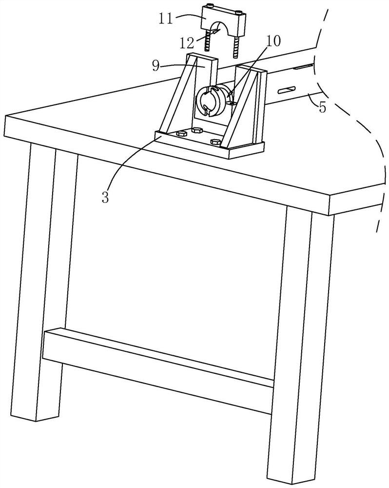
[0031] Attached to the following Figure 1-4 This application will be described in further detail.

[0032] The embodiment of the present application discloses a device for repairing an inflatable shaft. like figure 1 As shown, the inflatable shaft maintenance device includes a workbench 1 , a first clamping part 6 and a second clamping part 7 . A plurality of threaded holes are arranged on the table surface of the workbench 1 , and a first base 2 and a second base 3 are respectively detachably connected to the workbench 1 through screws. The first base 2 and the second base 3 are along the length of the workbench 1 . Orientation is set relative. A baffle plate is welded on the surface of the vertical table 1 on the first base 2, the cylinder body of the hydraulic cylinder 4 is penetrated and fixed in the baffle plate, the piston rod of the hydraulic cylinder 4 passes through the baffle plate, and the piston rod of the hydraulic cylinder 4 faces the second base 3 .

[003...


PUM


Abstract

The present application relates to a maintenance device for an inflatable shaft, which includes a workbench, a first clamping piece and a second clamping piece, the workbench is provided with a first base and a second base, the first base is provided with a hydraulic cylinder, and the first base is provided with a hydraulic cylinder. A clamping part is coaxially arranged at the end of the piston rod of the hydraulic cylinder, the first clamping part includes a first groove part and a first clamping head, the second clamping part is coaxially arranged at the inflation end of the inflatable shaft; The clamping part includes a second groove part and a second clamping head, a clamp for clamping the first clamping head and the second clamping head is arranged on the worktable, a first abutting plate is vertically arranged on the second base, and the first clamping head is arranged on the working table. An opening for the inflatable shaft to pass through is formed through the plate, and an annular groove is coaxially provided at one end of the inflatable shaft away from its inflatable end. The second abutting plate is connected, and the second abutting plate is provided with an arc-shaped groove which is clamped and connected with the annular groove. The present application has the effect of facilitating the drawing of the inflatable tip.

Description

technical field [0001] The present application relates to the field of maintenance of air shafts, and in particular, to a device for repairing air shafts. Background technique [0002] At present, the inflatable shaft is a commonly used part on the paper splicing machine. The winding or unwinding of the paper splicing machine is usually realized by the inflatable shaft, that is, the surface can protrude after being inflated by high pressure, and the surface can be quickly retracted after deflation. [0003] In the related art, the Chinese patent with the publication number CN210099953U discloses an air rod maintenance device, which includes two vertical and oppositely arranged installation plates, two A set of clamping components for clamping the gas rods are installed on each block mounting plate; the clamping components include a base and a U-shaped clamp, one end of the U-shaped clamp is hinged on the base, and the other end is a free end and is fixed on the base by a loc...

Claims


Application Information

Patent Timeline
Patent Type & Authority Patents(China)
IPC IPC(8): B25H1/02B25B27/02B25H1/08B25B11/02
CPCB25H1/02B25H1/08B25B27/026B25B11/02
Inventor 陈一亭
Owner 上海贝承机械制造有限公司
Learn More