Radiation-resistant laser cleaning irradiation tool based on pneumatic rotary motor, cleaning method thereof and laser cleaning machine
A rotary motor and laser cleaning technology, applied in the field of radiation-resistant laser cleaning irradiators, can solve the problem that laser irradiators cannot tolerate radiation, and achieve the effects of saving equipment space, saving energy, and improving adaptability
- Summary
- Abstract
- Description
- Claims
- Application Information
AI Technical Summary
Problems solved by technology
Method used
Image
Examples
Embodiment 1
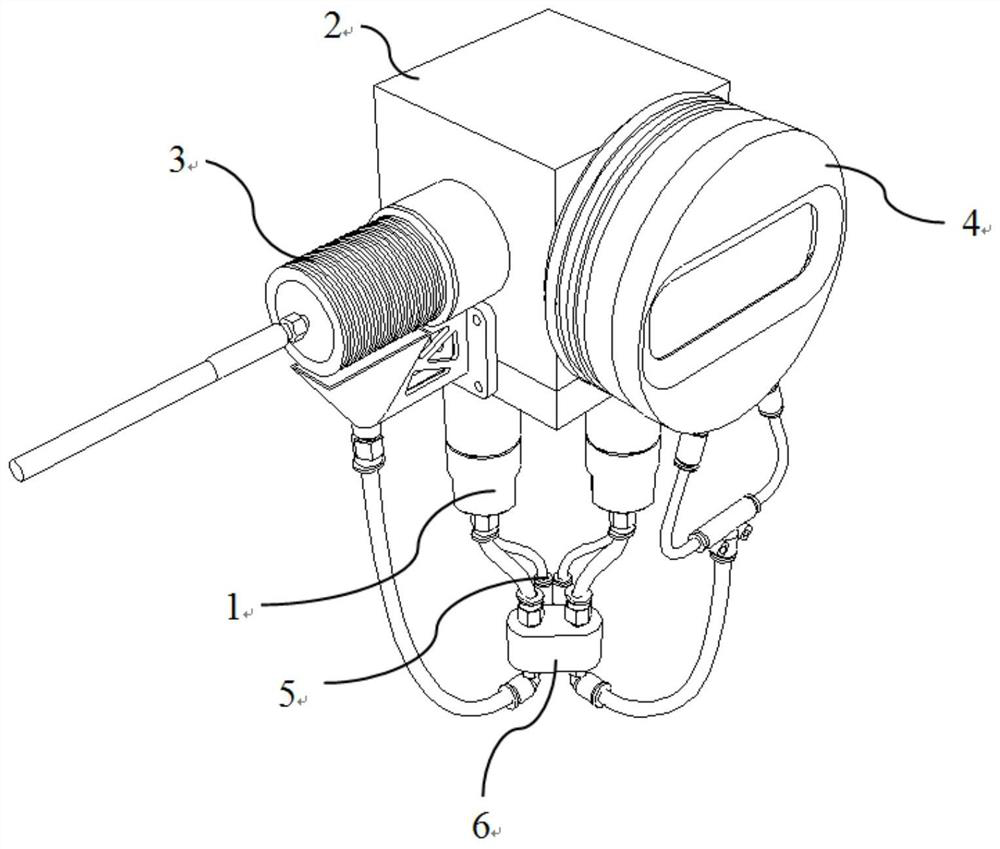
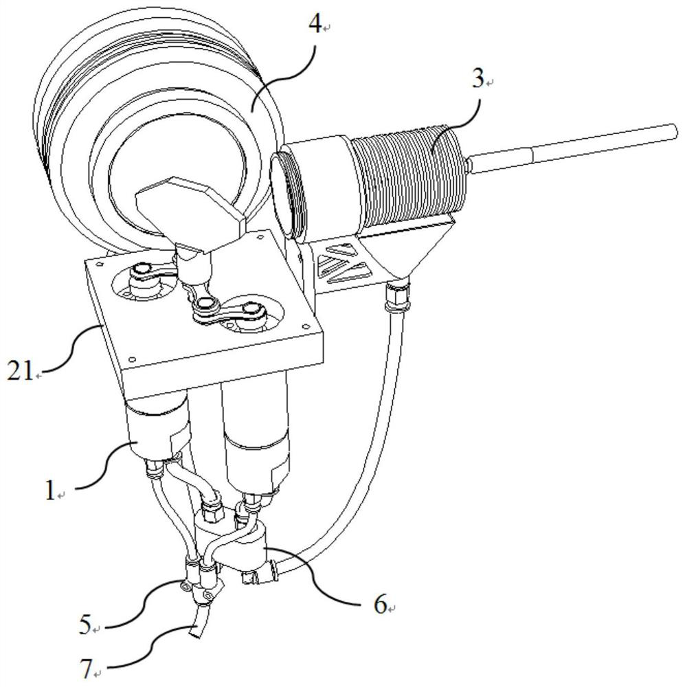
[0058] A radiation-resistant laser cleaning irradiation device based on a pneumatic rotary motor, including a pneumatic galvanometer assembly 1, a collimator assembly 3, a flat field lens assembly 4, and a housing assembly 2 that seals the laser light path, wherein:
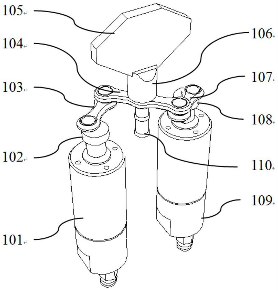
[0059] The pneumatic vibrating mirror assembly 1 includes a pneumatic rotary motor, a crank connecting rod driven by the pneumatic rotary motor, a rocker driven by the crank connecting rod to swing, and a rocker fixed on the swing shaft of the rocker to swing with it. The oscillating mirror, wherein the pneumatic rotary motor is driven by the compressed air fed into the intake pipe 7, and the exhaust gas is discharged from the exhaust gas discharge pipe. The flat field mirrors of the mirror assembly 4 are aligned to reflect the laser beam.
[0060] In radioactive decontamination operations, laser cleaning generally only requires the oscillating mirror to vibrate at a fixed amplitude, and the oscillating motion of...
Embodiment 2
[0074] In order to ensure the sealing of the laser light path, the housing assembly includes a motor base 201 and a housing 202 fixed on the motor base 201, and an assembly hole for assembling the pneumatic rotary motor is formed on the motor base 201 , the center of the one-piece rocker 104 is rotatably connected to the motor base 201 through the rocker bearing 110, and a space for accommodating the vibrating mirror is formed in the housing 202, and the adjacent two side walls of the housing 202 A mounting hole 204 for a collimator and a mounting hole 205 for a flat field lens are respectively formed for the laser light path to pass through.
[0075] The laser light collimated by the collimator assembly 3 enters the casing 202 through the collimator mounting hole 204, is reflected by the galvanometer lens 105, passes through the casing 202 through the flat field lens mounting hole 205, and finally passes through the flat field lens assembly 4 focus.
[0076] As a preferred m...
Embodiment 3
[0078] In order to ensure a good collimation effect, the collimator assembly 3 includes a collimator housing 301, a collimator mirror 302 installed in one end of the collimator housing, and a collimator mirror 302 installed in the other end of the collimator housing 301. Fiber 304 .
[0079] The collimator housing 301 is a cylindrical structure with one end sealed (not a seal, with a small hole for installing an optical fiber) and one end opened, the collimator mirror 302 is assembled at one end of the opening, and the optical fiber 304 is installed at one end of the seal, and The ends of the optical fibers 304 are located within the cylindrical structure.
[0080] There is a small amount of scattering of the laser in the collimator and is absorbed by the collimator, which will cause the collimator to heat up when used for a long time. Therefore, in order to speed up the heat dissipation of the collimator, the outer surface of the collimator housing 301 is Radiating fins 303 ...
PUM
 Abstract
Description
Claims
Application Information
 - Generate Ideas
- Intellectual Property
- Life Sciences
- Materials
- Tech Scout
- Unparalleled Data Quality
- Higher Quality Content
- 60% Fewer Hallucinations
Browse by: Latest US Patents, China's latest patents, Technical Efficacy Thesaurus, Application Domain, Technology Topic, Popular Technical Reports.
© 2025 PatSnap. All rights reserved.Legal|Privacy policy|Modern Slavery Act Transparency Statement|Sitemap|About US| Contact US: help@patsnap.com


