A self-powered buffer reset integrated device and its application method
A self-supplied energy and equipment technology, applied in the direction of electromechanical devices, control of mechanical energy, mechanical equipment, etc., can solve the problems of frequent oil leakage and other accidents, complex structure of brakes, heavy maintenance work, etc. force, the effect of eliminating the eccentricity problem
- Summary
- Abstract
- Description
- Claims
- Application Information
AI Technical Summary
Problems solved by technology
Method used
Image

Examples
Embodiment 1
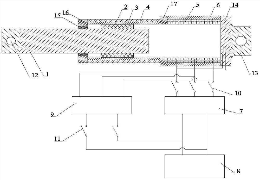
[0037] Such as figure 1 As shown, a self-powered buffer reset integrated device includes a mover module, a stator module and an energy feed module.
[0038] The mover module includes a straight rod 1 and a permanent magnet group 2. The straight rod 1 is a section of solid or hollow tube. The straight rod 1 passes through the central holes of the first flange 16 and the second flange 17 in sequence, and Linear motion is performed in the cavity of the inner tube 3 and the coil winding 5, and the permanent magnet group 2 is fixedly connected to the outer periphery of the straight rod 1, and moves linearly together with the straight rod 1. An air gap is formed between the permanent magnet group 2 and the inner tube 3 , and an air gap is formed between the permanent magnet group 2 and the coil winding 5 . One end of the straight rod 1 protrudes from the inner tube 3 , and the protruding end of the straight rod 1 is provided with a first connecting piece 12 .
[0039]The stator mo...
Embodiment 2
[0047] The difference between this embodiment and Embodiment 1 is the structure of the permanent magnet group 2. In this embodiment, the permanent magnet group 2 includes several annular permanent magnets, and all the annular permanent magnets are distributed parallel to the axis of the straight rod 1. Half of the annular permanent magnets are magnetized in the radial direction, and half of the annular permanent magnets are magnetized in the axial direction, and form a Halbach magnetic circuit parallel to the axial direction of the straight rod 1 .
Embodiment 3
[0049] Such as figure 1 As shown, a method for using a self-powered buffer reset integrated device, using a self-powered buffer reset integrated device such as embodiment 1 or embodiment 2, including:
[0050] When the transmitting equipment is working, the charging switch 10 is closed and the discharging switch 11 is opened. At this time, the straight rod 1 is driven by the launching equipment, and the straight rod 1 drives the permanent magnet group 2 to make linear motion together in the cavity of the conductive inner tube 3 . It can be seen from the principle of electromagnetic induction that when the conductive inner tube 3 and the permanent magnet group 2 move relative to each other, an induced eddy current will be generated in the inner tube 3, and the induced eddy current will interact with the permanent magnet group 2 to generate a barrier that hinders the straight rod 1 and the launch The damping force of the equipment movement makes the straight rod 1 and the launc...
PUM
 Abstract
Description
Claims
Application Information
 - R&D
- Intellectual Property
- Life Sciences
- Materials
- Tech Scout
- Unparalleled Data Quality
- Higher Quality Content
- 60% Fewer Hallucinations
Browse by: Latest US Patents, China's latest patents, Technical Efficacy Thesaurus, Application Domain, Technology Topic, Popular Technical Reports.
© 2025 PatSnap. All rights reserved.Legal|Privacy policy|Modern Slavery Act Transparency Statement|Sitemap|About US| Contact US: help@patsnap.com