Eureka AIR delivers breakthrough ideas for toughest innovation challenges, trusted by R&D personnel around the world.

Die bonder

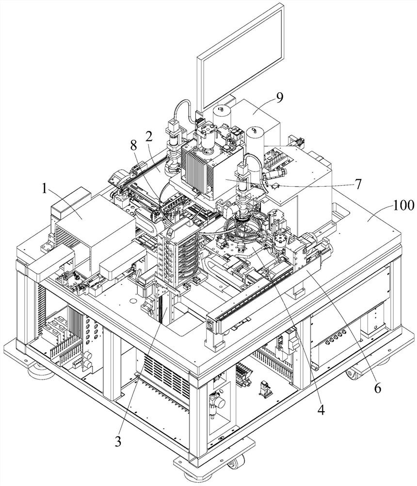
A die-bonding machine and die-bonding technology, which is applied to conveyor objects, semiconductor/solid-state device manufacturing, electrical components, etc., can solve the problems affecting die-bonding efficiency, slow loading and unloading rate of crystal rings, and low suction nozzle efficiency. Achieve automatic replacement operation, improve die bonding efficiency, and high efficiency

Active Publication Date: 2021-10-01
SHENZHEN XINYICHANG TECH CO LTD
View PDF0 Cites 0 Cited by
  • Summary
  • Abstract
  • Description
  • Claims
  • Application Information

AI Technical Summary

Problems solved by technology

[0003] The purpose of the embodiment of the present application is to provide a crystal bonding machine to solve the problems existing in the related art: the efficiency of manually replacing the suction nozzle is low, and the loading and unloading rate of the crystal ring is slow, which affects the efficiency of the crystal bonding

Method used


Image

  • Die bonder
  • Die bonder
  • Die bonder

Examples


Embodiment Construction

[0050] In order to make the technical problems, technical solutions and beneficial effects to be solved by the present application clearer, the present application will be further described in detail below in conjunction with the accompanying drawings and embodiments. It should be understood that the specific embodiments described here are only used to explain the present application, and are not intended to limit the present application.

[0051] It should be noted that when an element is referred to as being “fixed” or “disposed on” another element, it may be directly on the other element or be indirectly on the other element. When an element is referred to as being "connected to" another element, it can be directly connected to the other element or indirectly connected to the other element.

[0052]In addition, the terms "first" and "second" are used for descriptive purposes only, and cannot be interpreted as indicating or implying relative importance or implicitly specifyi...


PUM


Abstract

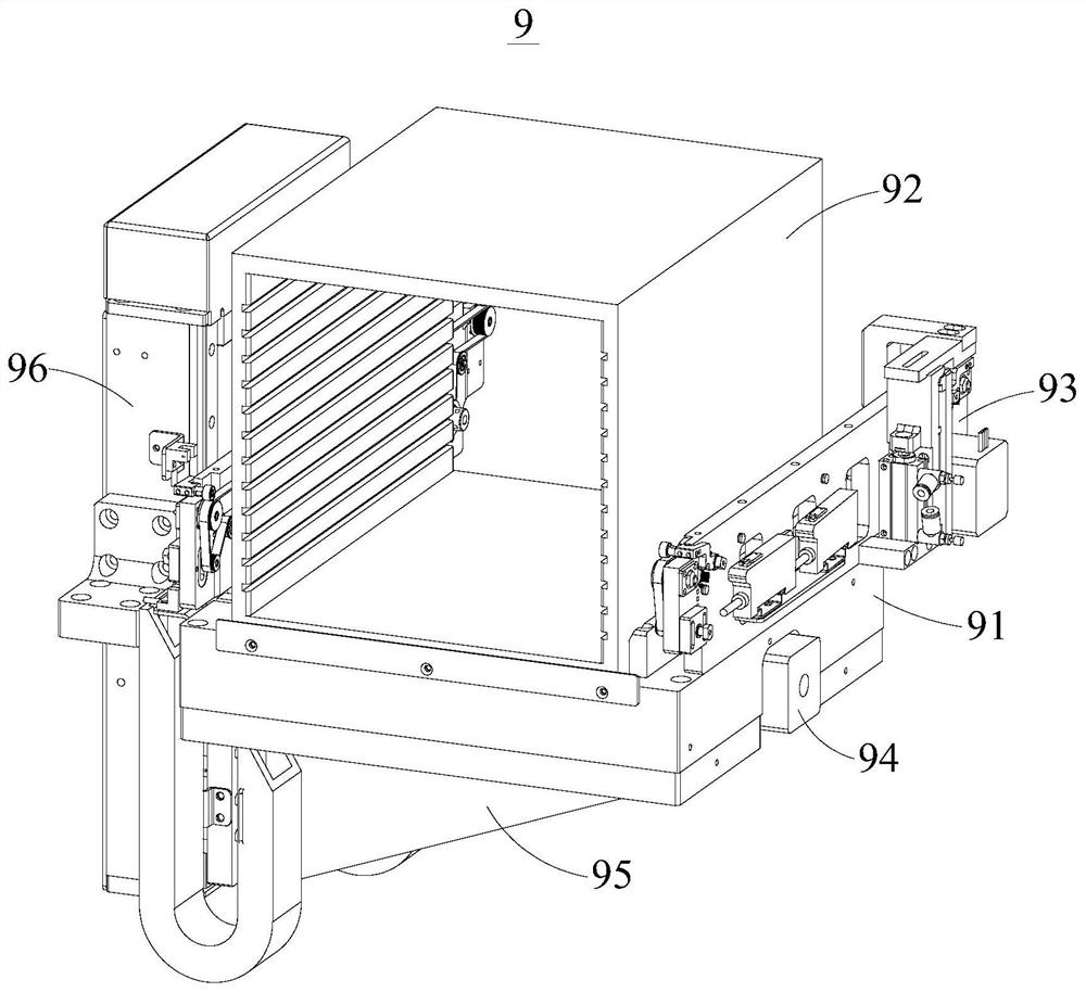
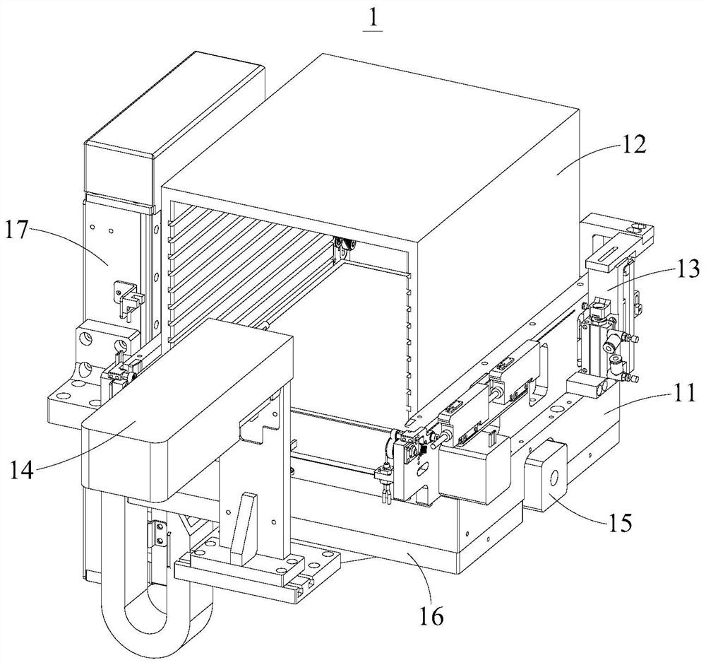
The application provides a crystal bonding machine, which includes a frame, a bracket feeding component, a bracket transferring component, a crystal ring feeding component, a crystal ring rotating component, a top crystal component, a crystal ring transferring component, a suction nozzle, a solid crystal Swing arm assembly, suction nozzle supply assembly and material receiving assembly. The bracket can be supplied to the bracket transfer component through the bracket feeding component, and the crystal ring on the crystal ring feeding component can be transferred to the crystal ring transfer component through the crystal ring transfer component, and the crystal ring rotation component can be used After the crystal ring is removed, the wafer on the crystal ring can be ejected to the crystal supply position through the crystal top assembly, and the wafer at the crystal supply position can be transferred to the support transfer assembly through the suction nozzle and the solid crystal swing arm assembly. Complete the die bonding operation of the wafer and the bracket. The crystal ring transfer component can realize the simultaneous operation of crystal ring loading and unloading, which reduces the waiting time for crystal ring loading and unloading, and helps to improve the efficiency of die bonding. Moreover, the automatic replacement of the suction nozzles can be realized through the suction nozzle receiving and supplying assembly, which saves time and labor and has high efficiency.

Description

technical field [0001] This application belongs to the technical field of crystal bonding, and more specifically relates to a crystal bonding machine. Background technique [0002] In the die-bonding equipment, the wafer is usually transported from the die-supply position to the die-bonding position by the suction nozzle, so as to realize the die-bonding operation of the die and the support. For different wafers, different types of nozzles need to be used for adsorption. However, at present, the suction nozzle is usually replaced manually, which is inefficient. Moreover, the operation of placing the crystal ring containing the wafer on the crystal supply position and removing the used crystal ring from the crystal supply position is completed by the same mechanical arm, which leads to slow loading and unloading of the crystal ring. , thereby affecting the die bonding efficiency. Contents of the invention [0003] The purpose of the embodiment of the present application ...

Claims


Application Information

Patent Timeline
Patent Type & Authority Patents(China)
IPC IPC(8): H01L21/677H01L21/683H01L21/67
CPCH01L21/67144H01L21/67766H01L21/67775H01L21/67778H01L21/6838
Inventor 胡新平
Owner SHENZHEN XINYICHANG TECH CO LTD
Why Eureka
Eureka Blog
Learn More