Energy-saving water boiler
A technology for boiling water boilers and water inlets, applied in lighting and heating equipment, fluid heaters, etc., can solve problems such as inability to use hot water, waste of water heat preservation, etc., and achieve the effects of improving utilization, facilitating waste, and facilitating fixation
- Summary
- Abstract
- Description
- Claims
- Application Information
AI Technical Summary
Problems solved by technology
Method used
Image
Examples
Embodiment 1
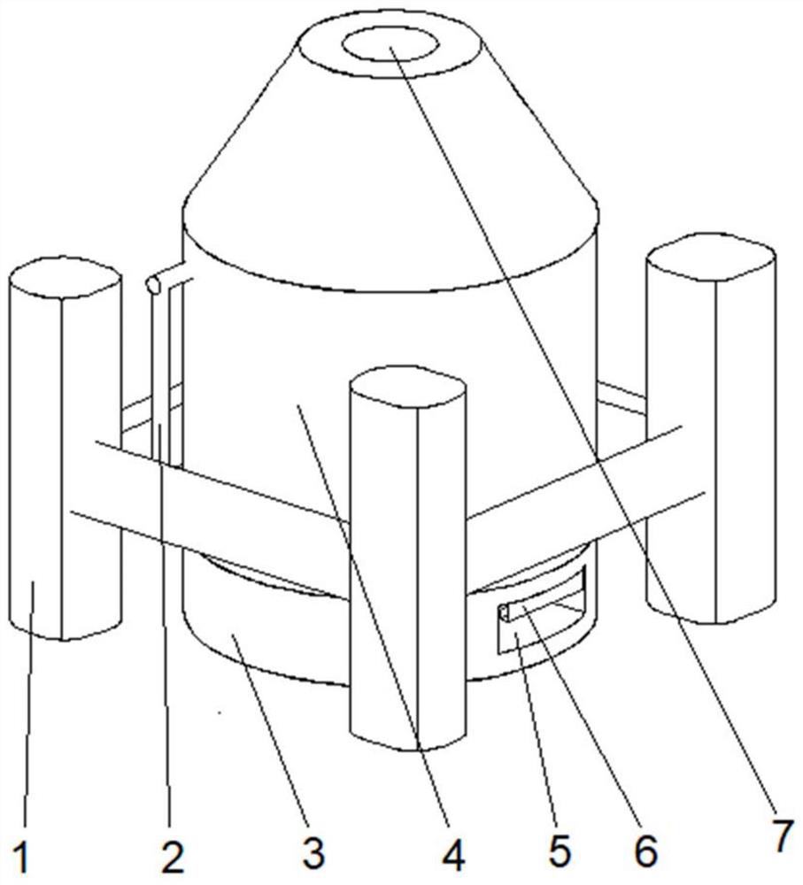
[0032] Such as Figure 1-2 , a technical solution proposed by the present invention: an energy-saving boiling water boiler, including a base 3, a cleaning port 5 is provided on the top right side of the front of the base 3, and a heater 6 is provided on the top of the inner wall on both sides of the cleaning port 5, The top of the base 3 is provided with a heating device 4, and both sides of the bottom of the heating device 4 are fixedly connected with a fixed frame 1, and the top of the heating device 4 is provided with an exhaust port 7, and the top left side of the front of the heating device 4 is connected with a connection Tube 2.
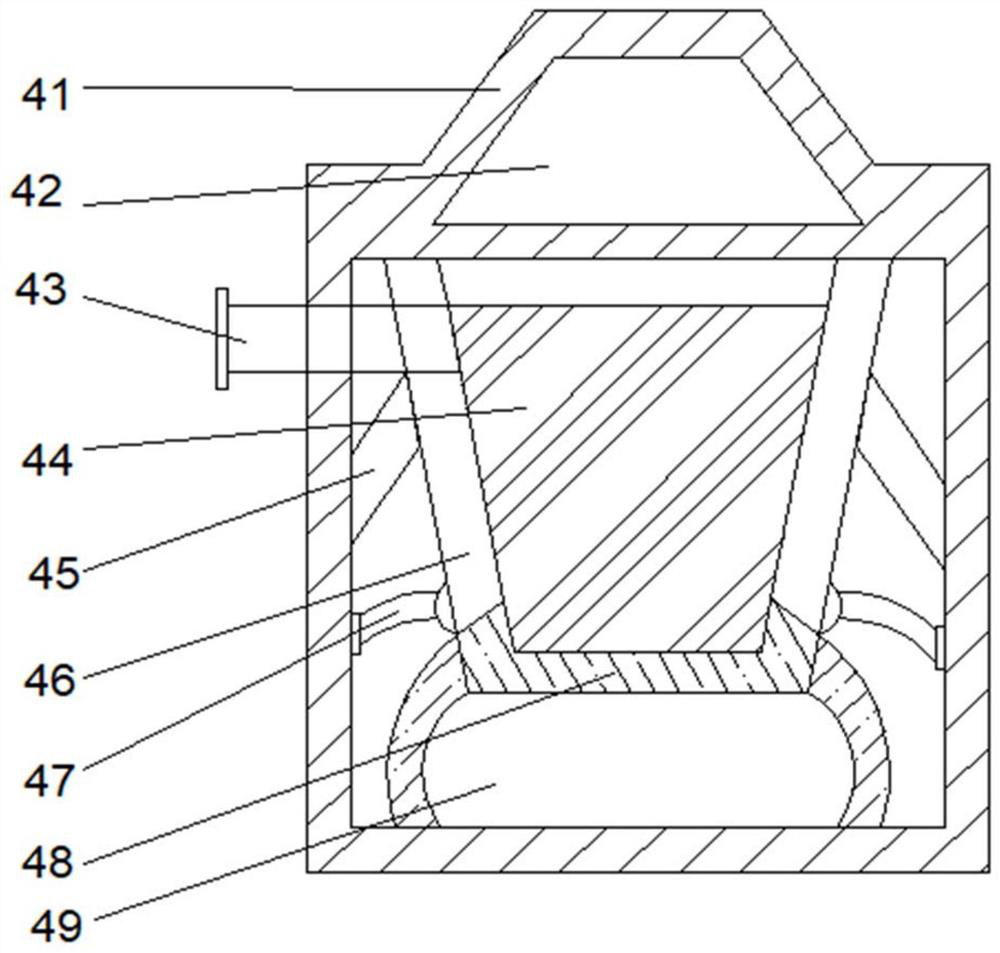
[0033]Wherein, the heating device 4 comprises a shell 41, the middle position of the inner cavity top of the shell 41 is provided with a flow guiding device 42, the inner cavity bottom of the shell 41 is provided with a heating cavity 49, and the top of the heating cavity 49 is fixedly connected with a carrier 48, the carrier The top of 48 is...
Embodiment 2
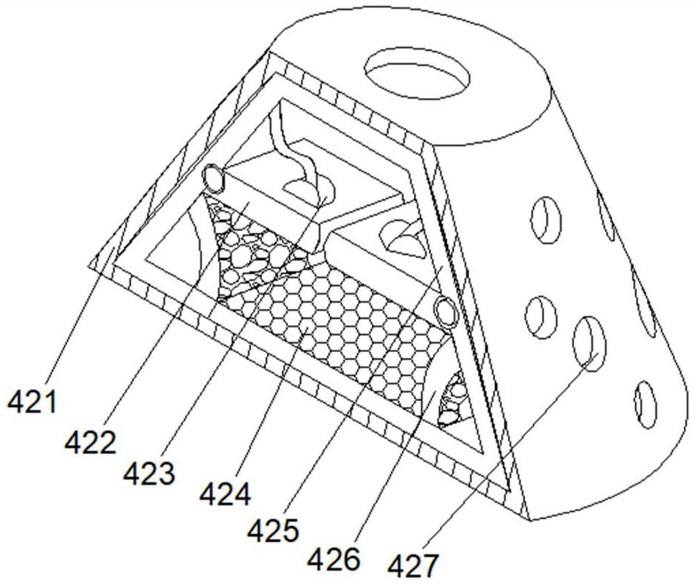
[0036] Such as Figure 1-3 As shown, on the basis of Embodiment 1, the present invention provides a technical solution: the flow guide mechanism 42 includes a flow guide cover 421, the outer surface of the flow guide cover 421 is provided with through holes 427, and the inner walls of both sides of the flow guide cover 421 Both are provided with a transition pipe 425, and a blocking mechanism 422 is provided in the middle of the inner wall on both sides of the shroud 421. The middle position of the top of the blocking mechanism 422 is fixedly connected with a reset rod 423, and the middle position of the inner cavity bottom of the shroud 421 is fixedly connected with a filter. The plate 424 and the bottom of the inner cavity of the flow guide cover 421 are located on both sides of the filter plate 424 and are fixedly connected with side plates 426 .
[0037] During use, inject water flow from the water inlet 43, heat in the heating cavity 49 by the heater 6, the heat that the ...
Embodiment 3
[0039] Such as Figure 1-5 As shown, on the basis of Embodiment 1 and Embodiment 2, the present invention provides a technical solution: the blocking mechanism 422 includes a baffle 4221, and the middle position of the inner cavity top of the baffle 4221 is fixedly connected with a receiving plate 4226, and the baffle 4221 The bottom of the cavity is fixedly connected with a bottom plate 4222, the middle position of the top of the bottom plate 4222 is provided with an auxiliary mechanism 4225, the top of the bottom plate 4222 is fixedly connected with support blocks 4224 on both sides of the auxiliary mechanism 4225, and the support block 4224 is set at a position away from the auxiliary mechanism 4225 There is a blocking block 4227, and the side of the blocking block 4227 close to the receiving plate 4226 is fixedly connected with a hook blocking block 4223.
[0040] Among them, the auxiliary mechanism 4225 includes a force-bearing block t1, an impact ball t4 is arranged at t...
PUM
 Abstract
Description
Claims
Application Information
 - R&D
- Intellectual Property
- Life Sciences
- Materials
- Tech Scout
- Unparalleled Data Quality
- Higher Quality Content
- 60% Fewer Hallucinations
Browse by: Latest US Patents, China's latest patents, Technical Efficacy Thesaurus, Application Domain, Technology Topic, Popular Technical Reports.
© 2025 PatSnap. All rights reserved.Legal|Privacy policy|Modern Slavery Act Transparency Statement|Sitemap|About US| Contact US: help@patsnap.com


