Droplet jetting device and related method
A droplet ejection and droplet technology, which is applied to ejection devices, liquid ejection devices, etc., can solve the problems of inability to guarantee droplet ejection efficiency, unstable droplet ejection direction, and difficulty in droplet ejection effect, etc. Droplet ejection performance, the effect of ensuring droplet ejection efficiency and stable droplet ejection direction
- Summary
- Abstract
- Description
- Claims
- Application Information
AI Technical Summary
Problems solved by technology
Method used
Image
Examples
Embodiment 1
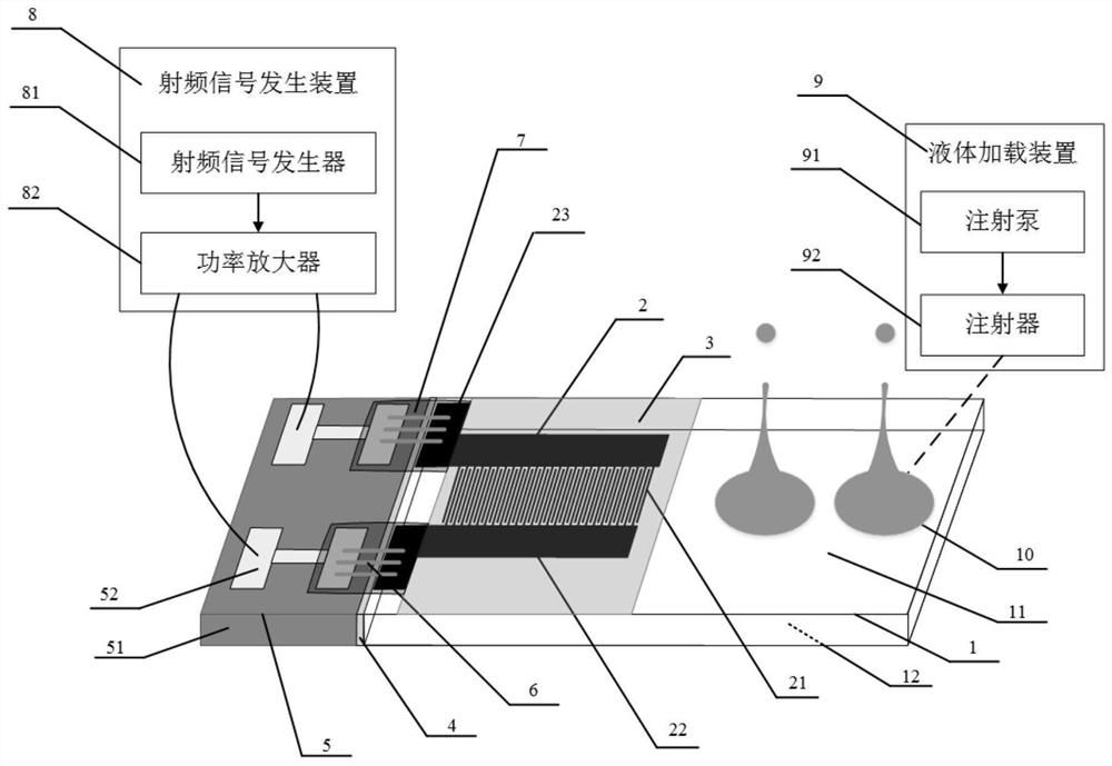
[0048] For a droplet ejection device provided in Embodiment 1 of the present disclosure, refer to figure 1 As shown, it includes: a piezoelectric chip 1, an interdigital transducer 2 arranged on the upper surface of the piezoelectric chip 1;
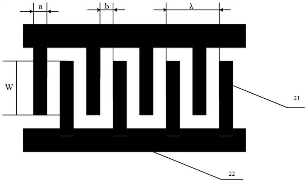
[0049] The ratio of the thickness of the piezoelectric chip 1 to the period of the interdigital transducer 2 is 1-3;
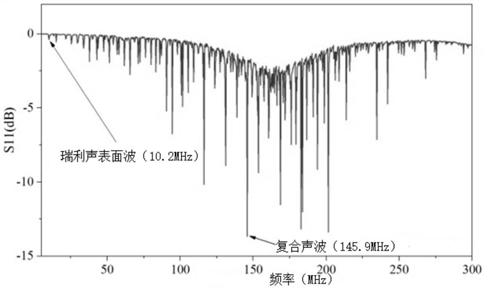
[0050] The interdigital transducer 1 is driven by a radio frequency signal to excite surface acoustic waves and bulk acoustic waves in the piezoelectric chip, and the surface acoustic waves and bulk acoustic waves are reflected on the upper surface 11 and the lower surface 12 of the piezoelectric chip 2 to form a composite Acoustic waves are used to drive the liquid to be driven on the liquid attachment area to stretch along the direction perpendicular to the surface of the piezoelectric chip to form a liquid column, so that the liquid column will have a droplet pinch-off effect at the end, and a single droplet will be e...
Embodiment 2
[0109] Based on the same inventive concept, an embodiment of the present disclosure also provides a method for manufacturing the droplet ejection device in the first embodiment above, including:
[0110] The interdigital transducer is evaporated on a surface of the piezoelectric chip, and the ratio of the thickness of the piezoelectric chip to the period of the interdigital transducer is 1-3.
[0111] In a specific embodiment, the preparation method of the droplet ejection device may specifically include the following steps:
[0112] (1) Lithium niobate (LiNbO 3 ) a polished surface of the piezoelectric chip 1 is vapor-deposited with an interdigital electrode metal film to obtain an interdigital transducer 2; and the ratio of the thickness h of the piezoelectric chip 1 to the period λ of the interdigital transducer 2 is 1 to 3 ;
[0113] (2) sputtering passivation layer film 3 on the surface of the interdigital electrode 21 and the bus electrode 22 area of the interdigital...
Embodiment 3
[0127] Based on the same inventive concept, an embodiment of the present disclosure also provides a droplet ejection method using any of the aforementioned droplet ejection devices, including:
[0128] delivering one or more liquids to be driven to the liquid attachment area; the liquid attachment area is located on the upper surface and / or lower surface of the piezoelectric chip 1 corresponding to the acoustic surface generated by the interdigital transducer 2 The area covered by waves propagating along the surface of the piezoelectric chip;
[0129] A radio frequency signal is applied to the interdigital transducer 2, and surface acoustic waves and bulk acoustic waves are excited in the piezoelectric chip 1, and the surface acoustic waves and bulk acoustic waves are reflected on the upper and lower surfaces of the piezoelectric chip 1 to form composite acoustic waves, driving The liquid to be driven is stretched in a direction perpendicular to the surface of the piezoelectri...
PUM
 Abstract
Description
Claims
Application Information
 - Generate Ideas
- Intellectual Property
- Life Sciences
- Materials
- Tech Scout
- Unparalleled Data Quality
- Higher Quality Content
- 60% Fewer Hallucinations
Browse by: Latest US Patents, China's latest patents, Technical Efficacy Thesaurus, Application Domain, Technology Topic, Popular Technical Reports.
© 2025 PatSnap. All rights reserved.Legal|Privacy policy|Modern Slavery Act Transparency Statement|Sitemap|About US| Contact US: help@patsnap.com


