
Air high-temperature treatment device

A high-temperature treatment and air extraction device technology, applied in deodorization, disinfection, etc., can solve the problems that air viruses or germs cannot be completely and effectively killed, disinfectant is harmful to health, and there is no disinfectant, so as to improve the utilization rate of heat energy and reduce Effect of heat loss and sufficient degree assurance

Pending Publication Date: 2021-06-08
崔文德
View PDF8 Cites 0 Cited by
  • Summary
  • Abstract
  • Description
  • Claims
  • Application Information

AI Technical Summary

Problems solved by technology

[0002] At present, air disinfection is basically based on disinfectant spraying and spraying, supplemented by some means such as ultraviolet radiation, but these methods cannot completely and effectively kill viruses or bacteria in the air
There are two disadvantages in spraying and spraying disinfectant. One is that there is no complete broad-spectrum disinfectant. The other is that although spraying or spraying disinfectant can partially kill or sterilize, the residual disinfectant itself is harmful to health; There is a problem of incomplete anti-virus, and in order to prevent personal injury, it is very inconvenient for people to leave the site during disinfection

Method used


Image

  • Air high-temperature treatment device
  • Air high-temperature treatment device
  • Air high-temperature treatment device

Examples


Embodiment Construction

[0038] In order to have a clearer understanding of the technical solutions, objectives and effects of the present invention, the specific implementation manners of the present invention will now be described with reference to the accompanying drawings.

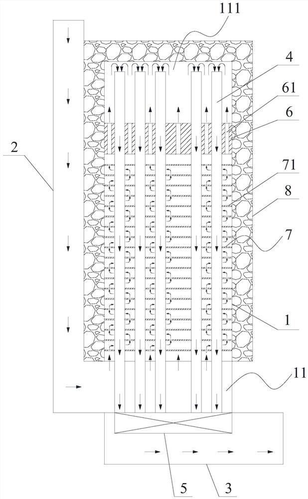
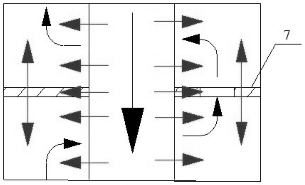
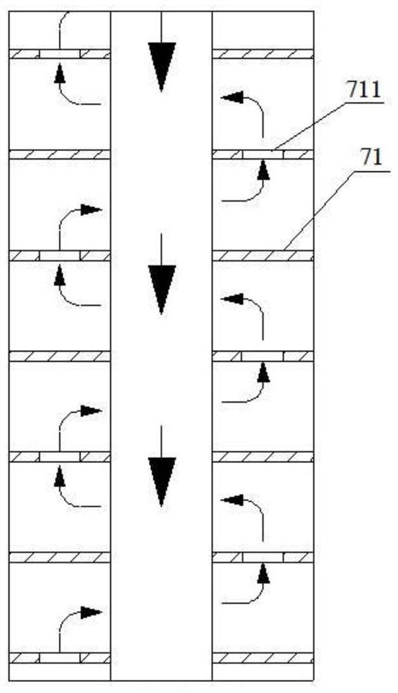
[0039] Such as figure 1 As shown, the present invention provides a high-temperature air treatment device, wherein the high-temperature air treatment device includes a main body 1, an air inlet pipe 2, a plurality of gas conduits 4, an air outlet pipe 3, an air extraction device 5 and a temperature control assembly 6, and the main body A chamber 11 is formed inside the chamber 1, and a plurality of gas conduits 4 are vertically arranged inside the chamber 11 at intervals. The upper end of the upper end of the chamber extends to the top of the chamber 11, the air inlet pipe 2 communicates with the inside of the chamber 11 at the bottom of the chamber 11, the air extraction device 5 and the air outlet pipe 3 are all located under...


PUM

PropertyMeasurementUnit
thicknessaaaaaaaaaa
thicknessaaaaaaaaaa
thicknessaaaaaaaaaa

Abstract

The invention provides an air high-temperature treatment device. The air high-temperature treatment device comprises a main body, an air inlet pipeline, a plurality of air guide pipes, an air outlet pipeline, an air extraction device and a temperature control assembly; a cavity is formed in the main body; the multiple air guide pipes are vertically arranged in the cavity at intervals, and the lower end of each air guide pipe penetrates through a bottom plate of the main body to communicate with the outside of the main body; the upper ends of the air guide pipes extend to the top of the cavity; the air inlet pipeline communicate with the interior of the cavity at the bottom of the cavity; the air extraction device and the air outlet pipeline are arranged below the main body; the air extraction device communicates with the lower ends of the air guide pipes; the air outlet pipeline communicates with the air extraction device; the temperature control assembly is arranged in the cavity; and all the air guide pipes penetrate through the temperature control assembly. According to the air high-temperature treatment device, air is sterilized through high temperature, no harmful substance is left, no harm is caused to human bodies, people do not need to leave in the using process, and using is very convenient.

Description

technical field [0001] The invention relates to the technical field of air disinfection treatment, in particular to an air high temperature treatment device. Background technique [0002] At present, air disinfection is basically based on disinfectant spraying and spraying, supplemented by some means such as ultraviolet radiation, but these methods cannot completely and effectively kill viruses or germs in the air. There are two disadvantages in spraying and spraying disinfectant. One is that there is no complete broad-spectrum disinfectant. The other is that although spraying or spraying disinfectant can partially kill or sterilize, the residual disinfectant itself is harmful to health; There is the problem of incomplete anti-virus, and in order to prevent personal injury, it is very inconvenient for people to leave the site during disinfection. Contents of the invention [0003] The purpose of the present invention is to provide a high-temperature air treatment device, ...

Claims


Application Information

Patent Timeline
Patent Type & Authority Applications(China)
IPC IPC(8): A61L9/16
CPCA61L9/16
Inventor 崔文德
Owner 崔文德
Learn More