
Alternating-current motor rotor manufacturing and assembling machine and assembling method

An AC motor and rotor technology, applied in the manufacture of stator/rotor body, etc., can solve problems such as non-adjustment, dislocation of rotor and stator assembly, inability to clamp and limit the rotor, etc., to reduce assembly time, increase use occasions, avoid The effect of misalignment

Active Publication Date: 2021-06-04
浙江铁仁工具制造有限公司
View PDF6 Cites 3 Cited by
  • Summary
  • Abstract
  • Description
  • Claims
  • Application Information

AI Technical Summary

Problems solved by technology

[0005] The present invention can solve the problem that the existing equipment cannot be arbitrarily adjusted according to the size of the rotor and the stator within a certain range when the rotor and the stator are assembled, so that the rotor and the stator cannot be clamped, which reduces the use occasions of the equipment and reduces the This improves the applicability of the equipment, and at the same time, the rotor cannot be clamped and limited, and the rotor and the stator are prone to misalignment during assembly, so that the rapid assembly of the rotor and the stator cannot be realized, and the assembly failure of the rotor and the stator is prone to occur. This increases the time for assembling the rotor and the stator, etc.

Method used


Image

  • Alternating-current motor rotor manufacturing and assembling machine and assembling method
  • Alternating-current motor rotor manufacturing and assembling machine and assembling method
  • Alternating-current motor rotor manufacturing and assembling machine and assembling method

Examples


Embodiment Construction

[0033] The embodiments of the present invention will be described in detail below with reference to the accompanying drawings, but the present invention can be embodied in various ways of claims defined and covered.

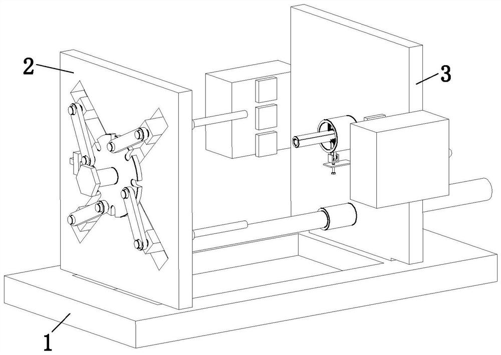
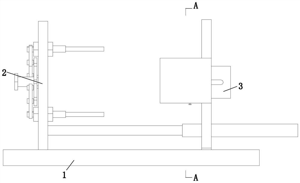
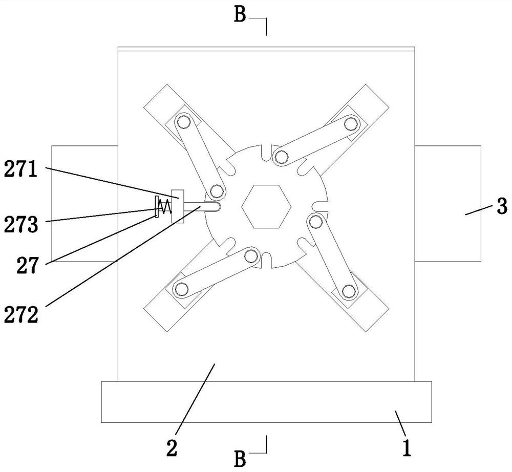
[0034] Such as Figure 1 to 8 As shown, a AC motor rotor manufacturing assembly assembly machine includes a plate 1, a support device 2, and a plug-in device 3, and the upper end of the placement plate 1 is connected to the support device 2 by sliding mating, and the upper end is away from the upper end The support device 2 is provided with a sleeve device 3, and the plug means 3 is mounted on the placement plate 1.

[0035] The support device 2 includes a slide plate 21, a rotating plate 22, a rotary screen 23, a transmission rod 24, a slide block 25, a placing mechanism 26, and a constant mechanism 27, and the upper end of the placed plate 1 is connected by sliding. The sliding plate 21, the slide plate 21 is connected to one end of the socchip device 3, and the rot...


PUM


Abstract

The invention relates to an alternating-current motor rotor manufacturing and assembling machine and an assembling method, the alternating-current motor rotor manufacturing and assembling machine comprises a placing plate, a supporting device and an inserting device, the upper end of the placing plate is connected with the supporting device in a sliding fit mode, the inserting device is arranged at the position, away from the supporting device, of the upper end of the placing plate, and the inserting device is installed on the placing plate. The machine can solve the problems that when an existing device is used for assembling a rotor and a stator, the rotor and the stator cannot be clamped according to the sizes of the rotor and the stator within a certain range, the use occasions of the device are reduced, the applicability of the device is reduced, meanwhile, the rotor cannot be clamped and limited, the rotor and the stator cannot be quickly assembled due to the fact that the rotor and the stator are easily dislocated during assembly, the rotor and the stator are easily failed to be assembled, and the assembly time of the rotor and the stator is increased.

Description

Technical field [0001] The present invention relates to the field of motor assembly, and in particular, to an alternating current motor rotor manufacturing assembly assembly machinery and assembly method. Background technique [0002] The composition of the AC motor includes two parts of the rotor and stator, the rotor and stator cooperation can achieve conversion between electrical energy and mechanical energy and mechanical energy and electrical energy, and the rotor of the AC motor is usually equipped with the stator; due to the huge development of the AC power system, The AC motor has become the most common motor; the AC motor structure is simple, easy to manufacture, is relatively strong, easy to make high speed, high voltage, large current, large capacity motor. [0003] At present, existing equipment is usually short enough when assembling the rotor and stator: 1. Existing equipment cannot be arbitrarily adjusted according to the rotor and the stator within a certain range...

Claims


Application Information

Patent Timeline
Patent Type & Authority Applications(China)
IPC IPC(8): H02K15/02
CPCH02K15/02
Inventor 不公告发明人
Owner 浙江铁仁工具制造有限公司
Learn More