
Adjustable heat preservation structure of air conditioner ventilation pipeline

An adjustable technology for ventilation pipes, applied in the direction of pipe protection, heat insulation protection of pipes, heat preservation, etc., can solve the problems of poor fixation of heat preservation structures, reduce the rationalization of air-conditioning ventilation pipe heat preservation structures, and no installation

Inactive Publication Date: 2021-06-04
顾兆辉
View PDF11 Cites 0 Cited by
  • Summary
  • Abstract
  • Description
  • Claims
  • Application Information

AI Technical Summary

Problems solved by technology

[0006] In order to solve the above-mentioned technical problems, the present invention provides an adjustable thermal insulation structure of air-conditioning ventilation ducts, to solve the problem that there is no installation method with flexible splicing and a structural device with strong fixation and softness in the thermal insulation structure of air-conditioning ventilation ducts , can not be flexibly matched and used according to the actual model size, which reduces the rationalization of the insulation structure of the air-conditioning ventilation duct, and the structural characteristics of the insulation structure are not strong enough and not soft enough, which leads to the insulation structure is easy to appear after installation It will gradually fall off, and at the same time it reduces the practicality of the insulation structure of the air-conditioning and ventilation ducts.

Method used


Image

  • Adjustable heat preservation structure of air conditioner ventilation pipeline
  • Adjustable heat preservation structure of air conditioner ventilation pipeline
  • Adjustable heat preservation structure of air conditioner ventilation pipeline

Examples


Embodiment

[0032] Append figure 1 Adherent Figure 7 Down:

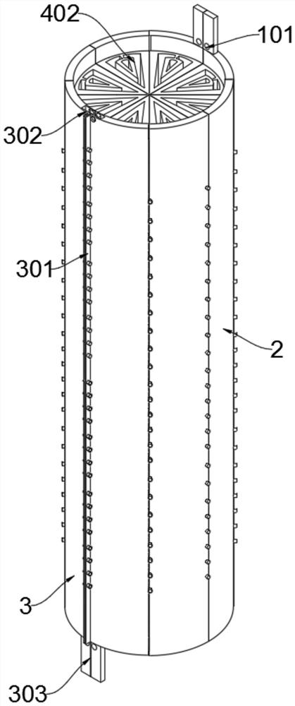
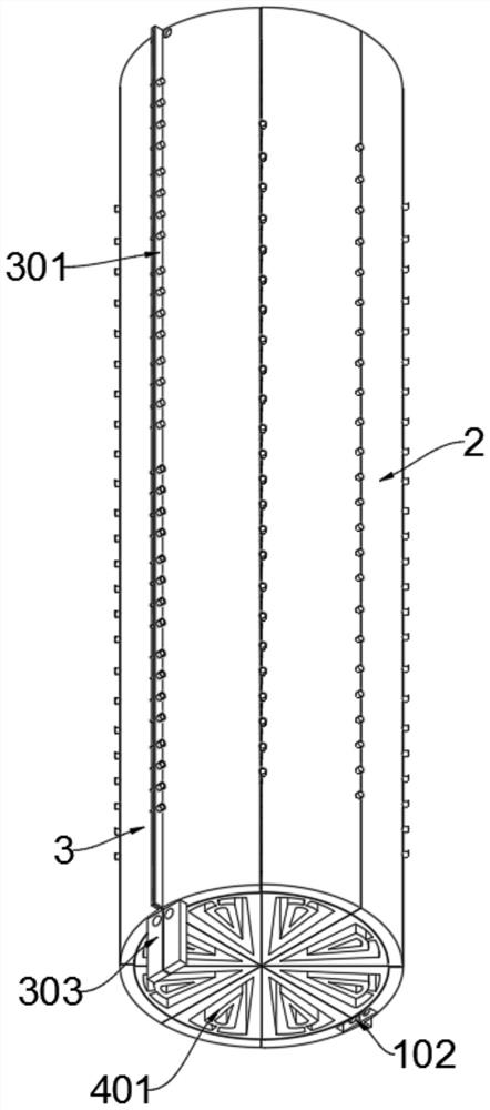
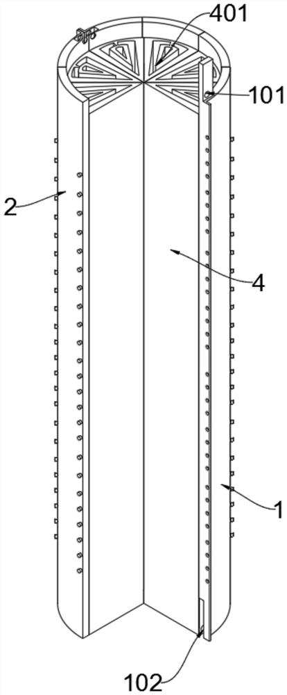
[0033] The present invention provides an insulation structure of an adjustable air conditioning venting conduit, comprising multiplying shell 1; multiplying housing 1 is a pair of irregular arc-shaped structures, and is connected to the outer end surface of the shell 1 to install a group Regular arc-shaped connecting case 2; on the outer end surface of the connecting case 2, a pair of arc-shaped closed shell 3; multiplied housing 1, the connecting case 2 and the housing 3 mounting to install a hollow The circular structure, and the center of the hollow circular structure vertically mounted a set of hollow filled blocks 4 composed of triangular bodies, including the upper housing 1 including a top slot 101 and a socket 102, one pair A pair of rectangular top slots 101 are fixed to the outer end surface of the casing 1, and the bottom bottom of the top slot 101 opens a pair of rectangular hollow rectangular alating grooves 102, multip...


PUM


Abstract

The invention provides an adjustable heat preservation structure of an air conditioner ventilation pipeline, relates to the technical field of exhaust systems, and aims to solve the problem that a structure device with a flexible splicing mounting mode and high fixity and flexibility is not mounted in the heat preservation structure of the air conditioner ventilation pipeline. The heat preservation structure of the air conditioner ventilation pipeline cannot be flexibly matched and used at will according to the actual model and size, rationalization of the heat preservation structure of the air conditioner ventilation pipeline is reduced, the heat preservation structure is prone to falling off gradually after being installed due to the structural characteristics that the heat preservation structure is not high in fixity and not soft enough, and meanwhile, the practicability of the heat preservation structure of the air conditioner ventilation pipeline is reduced. The adjustable heat preservation structure comprises upper shells, the upper shells are of a pair of irregular arc-shaped structures, and the outer side end faces of the upper shells are each provided with a set of irregular arc-shaped connecting shells in a connected mode. The outer side end faces of the right sides of the upper shells, the connecting shells and lower shells are each provided with a set of grooves.

Description

Technical field [0001] The present invention relates to the technical field of exhausting systems, and more particularly to an adjustable air conditioning air conditioning air conditioning. Background technique [0002] Air conditioning ventilation tube is a new type of pipeline formed by advanced machinery, which is mainly made of metal material, including galvanized plate, stainless steel, copper, aluminum and other materials, mainly used in air-conditioning industry ventilation systems, with use An adjustable air conditioning air-conditioning air insulation structure, and is widely used in family, buildings, factories, ships and large shopping malls, with convenient installation, fast and other advantages. [0003] Patent, for example, patent No. CN207702034U, the present invention discloses an insulation structure of an air conditioning venting conduit, comprising: a heat insulating plate, a caliber structure, and a locking structure, and the heat insulating plate is made of ...

Claims


Application Information

Patent Timeline
IPC IPC(8): F16L59/02F16L59/135F16L59/13
CPCF16L59/028F16L59/135F16L59/13
Inventor 顾兆辉
Owner 顾兆辉
Learn More