Winding device for textile processing

A winding device and winding technology, applied in transportation and packaging, conveying filamentous materials, thin material processing, etc., can solve the problem of less winding volume of textile threads, burning status, incomplete winding on the surface of winding rollers, etc. question

Active Publication Date: 2021-06-04
浙江金紫利新材料科技有限公司
View PDF9 Cites 0 Cited by
  • Summary
  • Abstract
  • Description
  • Claims
  • Application Information

AI Technical Summary

Problems solved by technology

[0005] 1. When the existing thread is wound on the winding roller, during the conveying process, its surface will rub against the conveying limit parts. According to the friction factor and the frictional heat conduction factor, the textile thread will be in the conveying process. The current situation of broken wires and burnt wires will affect the winding efficiency and cause cost losses
[0006] 2. The existing winding equipment utilizes the motor to drive the winding roller to rotate and wind the winding, and the winding roller and the limiting parts are all fixed at the same position, so that the textile thread can only be wound at the same position when winding. Winding is performed at the same position, resulting in uneven winding of the textile thread, resulting in incomplete winding on the surface of the winding roller, and a small amount of textile thread winding, which is not conducive to winding production

Method used


Image

  • Winding device for textile processing
  • Winding device for textile processing
  • Winding device for textile processing

Examples


Embodiment Construction

[0031] The following will clearly and completely describe the technical solutions in the embodiments of the present invention with reference to the accompanying drawings in the embodiments of the present invention. Obviously, the described embodiments are only some, not all, embodiments of the present invention. Based on the embodiments of the present invention, all other embodiments obtained by persons of ordinary skill in the art without making creative efforts belong to the protection scope of the present invention.

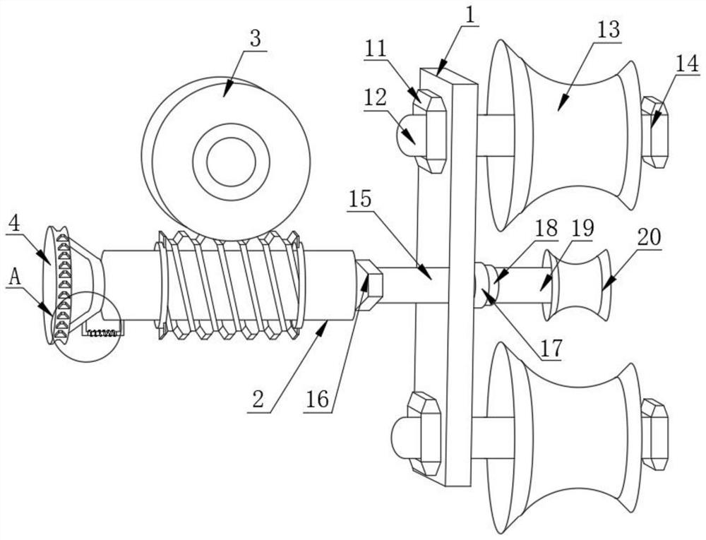
[0032] as attached Figure 1-5 The shown winding device for textile processing includes a winding limit assembly 1, one side of the winding limit assembly 1 is movably fitted with a reciprocating transmission assembly 2, and the top of the reciprocating transmission assembly 2 is movable A rotating tooth-missing part 3 is sleeved, and the other side of the rotating tooth-missing part 3 is movably fitted with a limit fixing component 4;

[0033] The upper and ...


PUM


Abstract

The invention discloses a winding device for textile processing. The winding device for the textile processing comprises a winding limiting assembly; a reciprocating transmission assembly is movably mounted on one side of the winding limiting assembly in a sleeving manner; a rotating tooth-missing piece is movably connected to the top of the reciprocating transmission assembly in a sleeving manner; a limiting and fixing assembly is movably mounted on the other side of the rotating tooth-missing piece in a sleeving manner; locking nuts are movably mounted on the upper side and lower side of the outer surface of the winding limiting assembly in a sleeving manner; a locking screw is movably clamped to the middle of each locking nut; and first transmission buffer rollers are movably mounted on the upper side and lower side of the outer surface of the other side of the winding limiting assembly in a sleeving manner. According to the winding device for the textile processing, by arranging the assemblies of the winding limiting assembly, the first transmission buffer rollers, a second transmission buffer roller and the like, the first transmission buffer rollers and the second transmission buffer roller are driven to rotate through the pulling of a spinning thread, the redundant spinning thread can be reserved in advance through a triangular stretching structure, the tensioning state of the spinning thread can be greatly relieved through the triangular stretching structure, the large pulling force is relieved, and the spinning thread is effectively prevented from being snapped by the pulling force.

Description

technical field [0001] The invention relates to the technical field of textile equipment, more specifically, the invention relates to a winding device for textile processing. Background technique [0002] Most of the current fabrics or clothing are processed and produced by textile technology, and in textile processing, materials such as cotton, linen or fiber need to be used. In the textile process, the textile thread needs to be wound first, which requires the use of Winding device. [0003] This equipment is mainly used to store the textile thread neatly during the process of textile thread winding, which is convenient for the production and processing of cloth or clothing. [0004] However, there are still some disadvantages in its actual use, such as: [0005] 1. When the existing thread is wound on the winding roller, during the conveying process, its surface will rub against the conveying limit parts. According to the friction factor and the frictional heat conducti...

Claims


Application Information

Patent Timeline
IPC IPC(8): B65H57/28B65H57/26B65H57/14B65H59/12B65H54/70B65H54/30
CPCB65H54/30B65H54/70B65H57/14B65H57/26B65H57/28B65H59/12
Inventor 陈景标
Owner 浙江金紫利新材料科技有限公司
Why Eureka
Try Eureka