Large-scale thermal modulation phase shifter driving method and system
A driving method and technology of a driving system, applied in the direction of pulse duration/width modulation, etc., can solve the problems that are not suitable for large-scale thermal phase shifter driving, and achieve low power consumption, low cost, and reduced power consumption and area Effect
- Summary
- Abstract
- Description
- Claims
- Application Information
AI Technical Summary
Problems solved by technology
Method used
Image

Examples
Embodiment 1
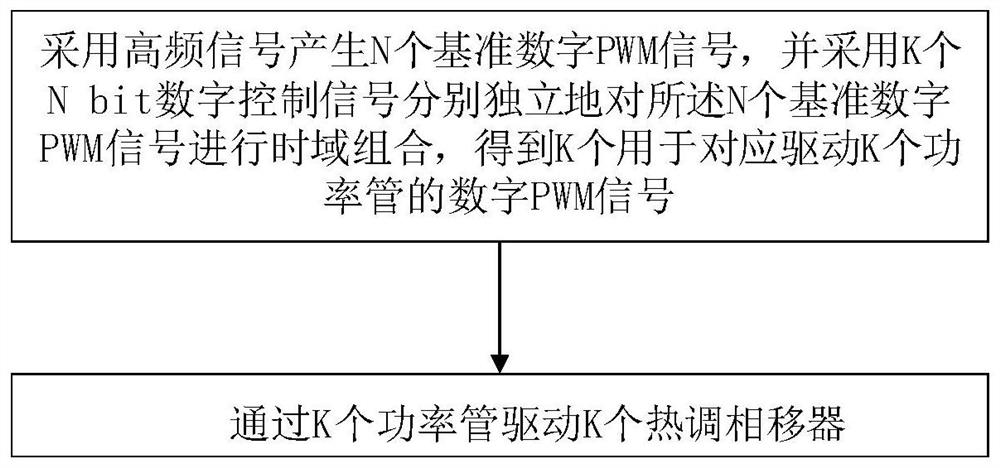
[0038] A driving method for a large-scale thermally adjustable phase shifter, such as figure 1 shown, including:
[0039] Using a high-frequency clock signal to generate N reference digital PWM signals, and using K N-bit digital control signals to independently combine the N reference digital PWM signals in the time domain to obtain K for correspondingly driving K power transistors digital PWM signal;
[0040] K thermal phase shifters are driven by K power tubes.
[0041] In this embodiment, by multiplexing N reference digital PWM signals, the power consumption and area of the overall driving scheme are reduced, and a small-area, low-cost, low-power consumption, high-efficiency large-scale thermally adjustable phase shifter drive is realized. This scheme can be used to drive the optical thermal phase shifter.
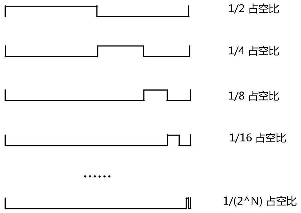
[0042] Preferably, the N reference digital PWM signals are: the period is the same as that of all the digital PWM signals used to drive the power tube, and the duty ...
Embodiment 2
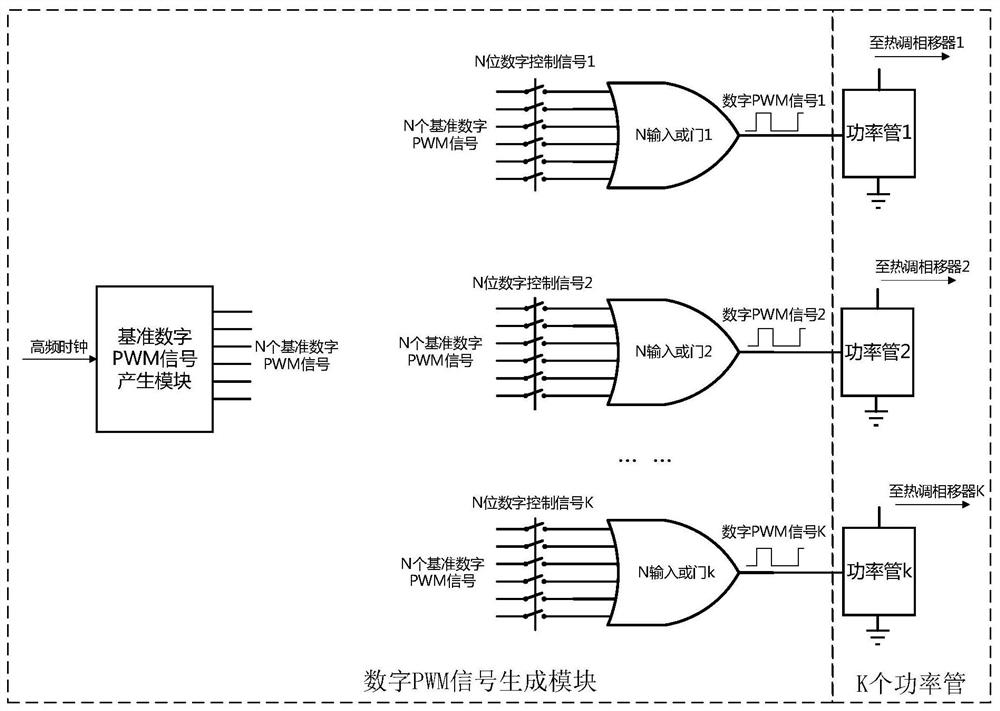
[0049] A driving system for a large-scale thermal phase shifter, including: a PWM signal generating module and K power tubes. Wherein, the PWM signal generation module is used to generate N reference digital PWM signals by using a high-frequency clock signal, and use K N bit digital control signals to independently perform time-domain combination on the N reference digital PWM signals to obtain K The digital PWM signal used to drive K power tubes correspondingly; the K power tubes are used to drive K thermal phase shifters.
[0050] Preferably, the PWM signal generation module includes: a reference signal generation unit and a combination unit.
[0051] The reference signal generation unit is used to process the high-frequency clock signal to generate N reference digital PWM signals; the combination unit includes K combination subunits, and each combination subunit is independently used to combine the N reference digital PWM signals Combining in the time domain and correspond...
example 1
[0058] Example 1: In a silicon-based optical phased array system, beam scanning is often achieved by controlling the phase relationship between the outgoing light waves of adjacent array elements, and phase adjustment often uses a thermally adjustable phase shifter to control the phase relationship. Therefore, a high-precision, linear thermal phase shifter phase adjustment is required to achieve high-precision beam scanning.
[0059] Such as Image 6 As shown, the thermally tunable phase shifter driving scheme based on Embodiment 1 or Embodiment 2 can be used to provide precise and linear phase adjustment to multiple thermally tunable phase shifters in a silicon-based optical phased array system, thereby achieving high Precision beam scanning. Compared with other solutions, this solution has the advantages of low power consumption, small area and high precision.
PUM
 Abstract
Description
Claims
Application Information
 - R&D
- Intellectual Property
- Life Sciences
- Materials
- Tech Scout
- Unparalleled Data Quality
- Higher Quality Content
- 60% Fewer Hallucinations
Browse by: Latest US Patents, China's latest patents, Technical Efficacy Thesaurus, Application Domain, Technology Topic, Popular Technical Reports.
© 2025 PatSnap. All rights reserved.Legal|Privacy policy|Modern Slavery Act Transparency Statement|Sitemap|About US| Contact US: help@patsnap.com