
Centrifugal machine with anti-shake guiding function

A centrifuge and functional technology, applied in the field of centrifuges, can solve the problems of large jitter, inability to remove impurities synchronously, incomplete separation and purification, etc., and achieve the effects of reducing jitter, improving the effect of slag aggregation, and completely separating and purifying

Pending Publication Date: 2021-06-01
云南精一电力科技有限责任公司
View PDF9 Cites 0 Cited by
  • Summary
  • Abstract
  • Description
  • Claims
  • Application Information

AI Technical Summary

Problems solved by technology

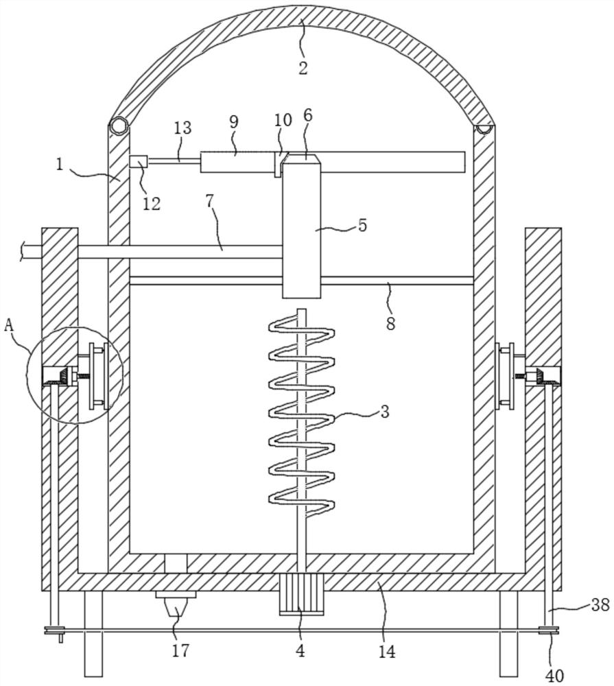
[0004] In order to solve the technical problem that the centrifuge in the prior art will produce large vibrations during use, resulting in incomplete separation and purification, and cannot simultaneously remove impurities floating on the liquid surface that are less than the density of the liquid during the centrifugation process, the present invention Provide a centrifuge with anti-shake guide function

Method used


Image

  • Centrifugal machine with anti-shake guiding function
  • Centrifugal machine with anti-shake guiding function
  • Centrifugal machine with anti-shake guiding function

Examples


Embodiment 1

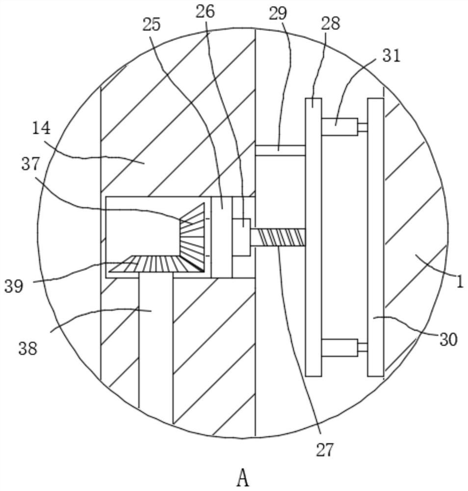
[0032] Please combine Figure 1 to Figure 6 , the centrifuge with anti-vibration guiding function includes an inner cylinder 1 and an outer cylinder 14 sleeved outside the inner cylinder 1 . In this embodiment, the top of the inner cylinder 1 is installed with a cylinder cover 2 matching it. The cylinder cover 2 is fixedly connected with the inner cylinder 1 to facilitate the opening or closing of the cylinder lid 2 on the inner cylinder 1 . The bottom of the outer cylinder 14 is provided with a drain valve 17 connected to the inside of the inner cylinder 1 , through which the centrifuged liquid in the inner cylinder 1 can be sequentially released. Support feet (not shown) are installed on the bottom of the outer cylinder 14, and are supported on the ground by the support frame.

[0033] The inner cylinder 1 is provided with a spiral stirring shaft 3, the stirring shaft 3 is an ascending spiral structure, and a motor 4 is installed at the bottom of the outer cylinder 14, and...

Embodiment 2

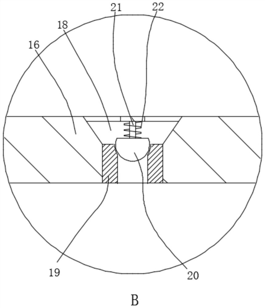
[0048] Please combine Figure 7 , this embodiment 2 is an improved solution of embodiment 1, specifically, the bottom of the inner cylinder 1 is provided with an overflow cover 16, and an air flow space is formed between the inner cylinder 1 and the overflow cover 16. A plurality of air outlet holes 18 with inverted trapezoidal cross-sections are opened on the top of the flow cover 16 . A valve seat 19 is arranged in the outlet hole 18 , and a valve ball 20 matched with the valve seat 19 is arranged in the outlet hole 18 above the valve seat 19 . The side of the valve ball 20 away from the valve seat 19 is connected to the cover body of the flow cover 16 through the telescopic rod one 21 . A spring 22 is sheathed on the outside of the telescopic rod 1 21 . An air pump 15 is installed on the bottom of the outer cylinder 14, and the air outlet end of the air pump 15 communicates with the airflow space through a conduit.

[0049] An inert gas that does not react with the liqui...


PUM


Abstract

The invention relates to the technical field of centrifugal machines, and discloses a centrifugal machine with an anti-shake guiding function. The centrifugal machine comprises an inner cylinder and an outer cylinder arranged on the outer side of the inner cylinder in a sleeving manner. A spiral stirring shaft is rotationally arranged in the inner cylinder, and a guide scum collecting device for collecting scum is arranged above the stirring shaft. An anti-shake device used for weakening shake of the inner cylinder is arranged between the inner cylinder and the outer cylinder. The anti-shaking device arranged between the inner cylinder and the outer cylinder can effectively weaken shaking generated when the cylinder body is used, separation and purification in the cylinder body are more thorough, meanwhile, the guide scum collecting device arranged in the cylinder body can timely collect scum which floats on the liquid surface and has the density smaller than that of the liquid in the centrifugal process, and the purity of the liquid obtained through centrifugal separation is guaranteed.

Description

technical field [0001] The invention relates to the technical field of centrifuges, in particular to a centrifuge with an anti-vibration guiding function. Background technique [0002] A centrifuge is a machine that uses centrifugal force to separate components in a mixture of liquid and solid particles or liquid and liquid. The centrifuge is mainly used to separate the solid particles or liquid in the suspension; or to separate two different densities and immiscible liquids in the emulsion; it can also be used to remove the liquid in the wet solid, and the special super speed Tubular separators can also separate gas mixtures of different densities; using the characteristics of different sedimentation velocities of solid particles of different densities or particle sizes in liquids, some decanter centrifuges can also classify solid particles according to density or particle size. [0003] However, the existing centrifuges will produce large vibrations during use, resulting ...

Claims


Application Information

Patent Timeline
Patent Type & Authority Applications(China)
IPC IPC(8): B04B11/08B04B15/00
CPCB04B11/08B04B15/00B04B2011/086
Inventor 童勇耿晓梅
Owner 云南精一电力科技有限责任公司
Learn More