Topological structure of n-path monolithic lumped power divider and design method thereof

A topology and power divider technology, applied in the direction of circuits, waveguide devices, electrical components, etc., can solve the problems of loss and layout area increase, circuit size and loss are not ideal, and achieve good port matching, wide applicability, The effect of minimal loss

Inactive Publication Date: 2021-05-28
XIDIAN UNIV
View PDF6 Cites 0 Cited by
  • Summary
  • Abstract
  • Description
  • Claims
  • Application Information

AI Technical Summary

Problems solved by technology

like figure 1 As shown, this power divider can be integrated on the chip, but because it uses 2 inductors, the loss and layout area are also greatly increased
There are also circuit structures that will figure 1 simplification, resulting in a more compact on-chip integrated power divider, using fewer components, such as figure 2 As shown, but because 2 or more inductors are still used in its circuit, the size and loss of the circuit are not ideal

Method used


Image

  • Topological structure of n-path monolithic lumped power divider and design method thereof
  • Topological structure of n-path monolithic lumped power divider and design method thereof
  • Topological structure of n-path monolithic lumped power divider and design method thereof

Examples


Embodiment 1

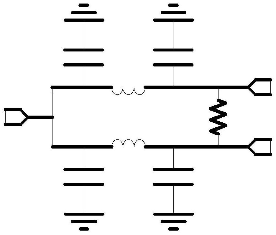
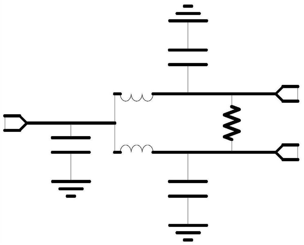
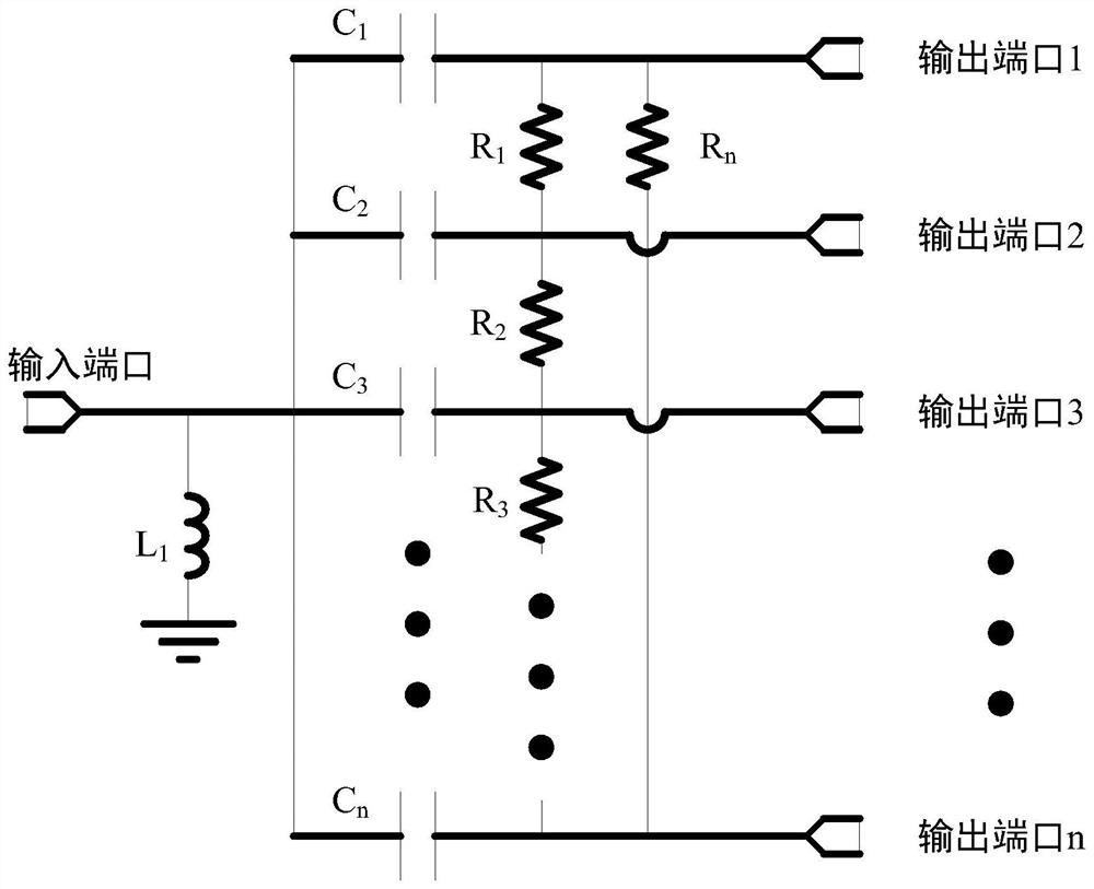
[0040] See image 3 , image 3 It is a structural schematic diagram of the topology of an n-way monolithic lumped power divider provided by an embodiment of the present invention. This embodiment provides a topological structure of an n-way single-chip lumped power divider, the topology of the n-way single-chip lumped power divider includes an inductor L 1 And n branches, n branches include n capacitors and n resistors, n capacitors are divided into capacitance C 1 to capacitance C n , n resistors are divided into resistors R 1 to resistor R n , where the inductance L 1 One end of the capacitor is connected to the input port, and the capacitor C 1 to capacitance C n One end of both is also connected to the input port, the inductance L 1 The other end of the ground, the capacitor C 1 to capacitance C n The other end of correspondingly connects the output port 1 to the output port n, that is, the capacitor C 1 The other end is connected to the output port 1, the capac...


PUM


Abstract

The invention discloses a topological structure of an n-path monolithic lumped power divider and a design method thereof. The topological structure comprises an inductor L1 and n branches, the n branches comprise capacitors C1 to Cn and resistors R1 to Rn, one end of the inductor L1 is connected with an input port, one ends of the capacitors C1 to Cn are connected with the input port, the other end of the inductor L1 is grounded, the other ends of the capacitors C1 to Cn are correspondingly connected with the output ports 1 to n, the resistors R1 to Rn-1 are respectively connected in parallel between two adjacent output ports, and the two ends of the resistor Rn are respectively connected with the output port 1 and the output port n. Compared with other power dividers, only one inductor is used, the total used element is 2n+1 (n is larger than or equal to 3), n-path power distribution can be achieved through the fewest elements, the simplest two-path power divider and the simplest three-path power divider are only composed of four elements and seven elements respectively, and therefore loss and circuit layout can be minimized, and high integration is achieved.

Description

technical field [0001] The invention belongs to the technical field of power splitters, and in particular relates to a topology structure of an n-way single-chip lumped power splitter and a design method thereof. Background technique [0002] The power splitter is a common circuit unit in the field of radio frequency and microwave. Its function is to decompose the input signal power into N signals with equal or unequal power, otherwise it is a power combiner. The power splitter is widely used in wireless communication, Satellite communications and phased array antennas. [0003] Common power splitters include Wilkinson power splitters, directional couplers, Lange couplers, and T-junctions. These power splitters are often implemented as microstrip circuits or waveguide units. Although the Wilkinson power divider implemented in the form of a microstrip circuit has the advantages of small size and easy processing, it is still not suitable for on-chip integration. As people's ...

Claims


Application Information

Patent Timeline
Patent Type & Authority Applications(China)
IPC IPC(8): H01P5/12
CPCH01P5/12
Inventor 马晓华周九鼎卢阳王语晨赵子越易楚朋刘文良
Owner XIDIAN UNIV
Why Eureka
Try Eureka