
Tensile machine for testing ductility of plastic rod

A ductility and tension machine technology, applied in the field of performance testing devices, can solve problems such as integrity damage, damage, and breakage, and achieve the effect of improving accuracy, ensuring integrity, and avoiding damage

Inactive Publication Date: 2021-05-28
兰春林
View PDF0 Cites 0 Cited by
  • Summary
  • Abstract
  • Description
  • Claims
  • Application Information

AI Technical Summary

Problems solved by technology

[0005] The technical problem to be solved by the present invention is to provide a tensile machine for testing the ductility of plastic rods. One of the purposes is to ensure that the plastic rods will not be damaged when they are clamped, so that the overall integrity of the rods can be maintained and the tensile force can be solved. When the plastic rod is clamped by the machine, the clamped parts of the two ends of the plastic rod will be deformed and damaged due to the clamping of the clamp, and its overall integrity will be destroyed. When performing a tensile test, it is easy to cause the overall force to be weak. Balanced, causing the plastic rod to break from both ends, which affects the test results; another purpose is to solve the problem that due to the material of the plastic rod itself, when the stress inside it is stretched to the threshold, it will not break. Make a sound, but the machine cannot remind the staff in time to stop the control device, and the machine will easily cause damage to itself if it continues to run, and will affect the test results, so as to achieve the effect of accurately collecting test data

Method used


Image

  • Tensile machine for testing ductility of plastic rod
  • Tensile machine for testing ductility of plastic rod
  • Tensile machine for testing ductility of plastic rod

Examples


Embodiment 1

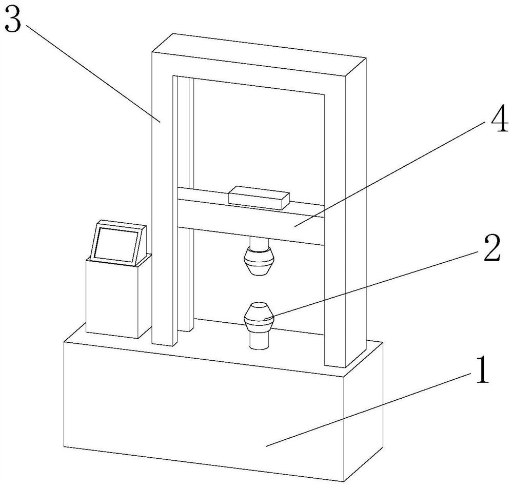
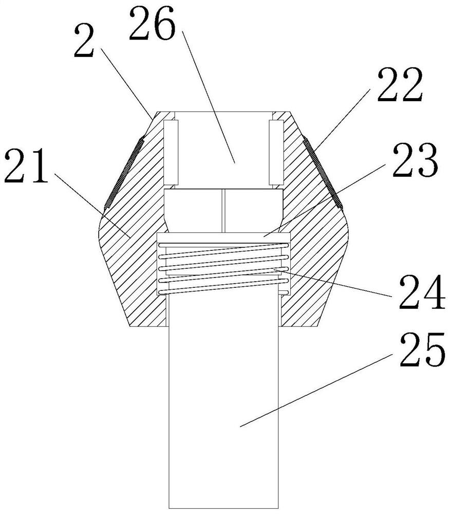
[0027]Such asFigure 1 - Figure 2 As shown, the present invention provides a tensile machine for a plastic rod ductility test, including a power control mechanism 1, a top fixed mounting finite mechanism 3 of the power control mechanism 1, and a stretch mechanism 4 is provided inside the limit mechanism 3, The stretch mechanism 4 is actively mounted inside the groove on both sides of the limit mechanism 3, and there is a clamping mechanism 2 between the stretch mechanism 4 and the power control mechanism 1, and the number of clamping mechanisms 2 is provided with two and mutual symmetry distribution. The bottom surface of the clamping mechanism 2 is fixedly welded, and the bottom surface of the other holding mechanism 2 is fixed to the bottom surface of the stretching mechanism 4, and the axis of the two clamping mechanisms 2 remains consistent, clamping The mechanism 2 includes a clamping body 21, and the outer wall of the holding body 21 is fixedly connected to a non-slip pad 22, a...

Embodiment 2

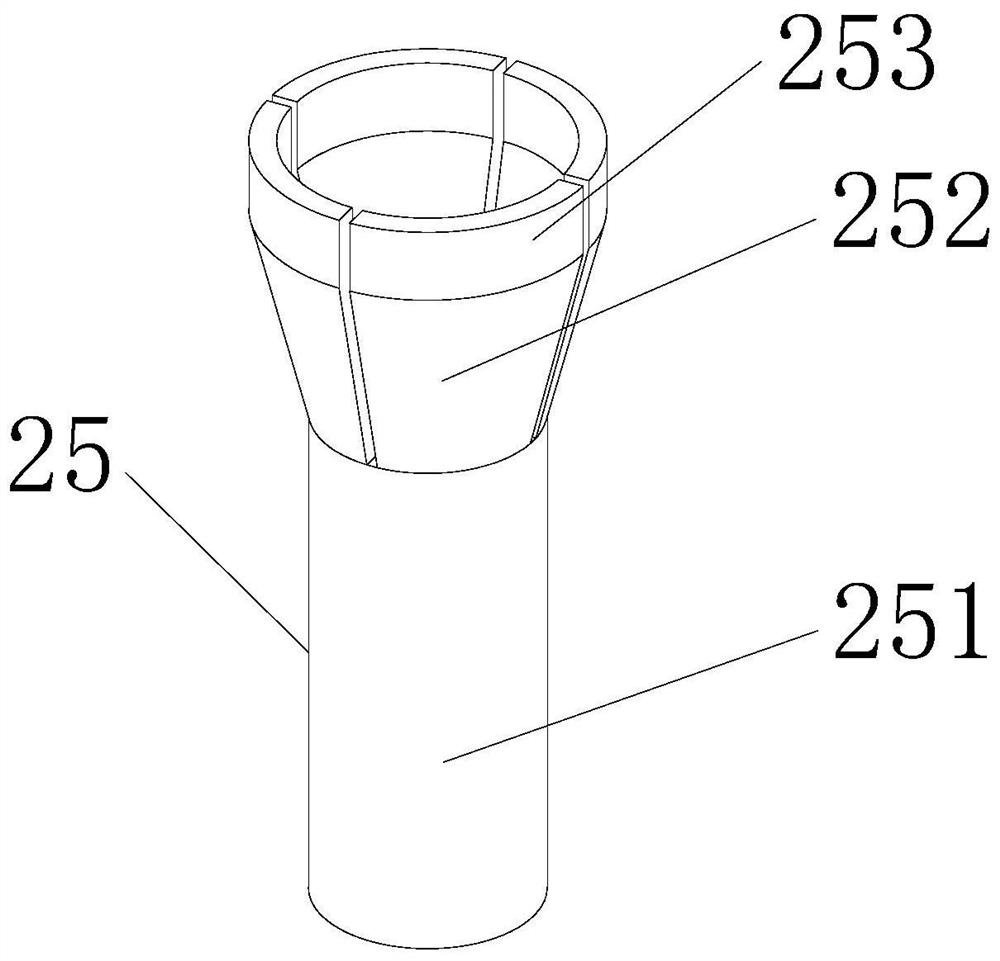
[0030]Such asFigure 3-5 As shown, in the basis of the first embodiment, the present invention provides a technical solution: the connection device 25 includes a support post 251, and the top portion of the support post 251 is fixedly connected to the clamping plate 252, and the number of clamping plate 252 is provided with four. And the equal distance is distributed, the top of the clamping plate 252 is fixedly coupled with the contact plate 253, and the support post 251 includes a cylinder 511, and the inner portion of the cylinder 511 is provided with a sound chamber 513, and the interior of the sound chamber 513 is provided with a vibration block 512, vibration. One end of the block 512 is fixedly coupled to the inner wall of the cylinder 511, and the inside of the vibration block 512 is provided with a knocking ball 121, a connecting rod 122, an active lumen 123, and one end of the connecting rod 122 and the inner wall of the vibration block 512. The other end of 122 is fixed to...

Embodiment 3

[0032]Such asFigure 6 As shown, in the basis of Example 1, Example 2, the present invention provides a technical solution: preferably, the contact plate 253 includes a plate body 531, and the plate body 531 is provided with an adsorption plate 532, and the adsorption plate 532 On one side, the active rod 533 is fixed, and the movable rod 533 is fixed to one side of the adsorption plate 532 fixedly connected to the pressure plate 535, and the inside of the plate body 531 is provided with a compression shrapnel 534, by using the adsorption plate 532, the compression shrapnel 534, the pressure plate 535 combined When the contact plate 253 is fixed to the outer wall of the plastic rod, the adsorption plate 532 is applied to the adsorbent plate 532, so that the adsorption plate 532 is extruded to the outer wall of the plastic rod, the inside of it. The air discharges forms a vacuum, and the outer atmospheric pressure is attached to the outer wall of the plastic rod, so that it is more st...


PUM


Abstract

The invention discloses a tensile machine for testing ductility of a plastic rod, and relates to the technical field of performance detection devices. The tensile machine comprises a power control mechanism, a limiting mechanism is fixedly mounted at the top of the power control mechanism, a stretching mechanism is arranged in the limiting mechanism, the stretching mechanism is movably mounted in grooves in the two sides of the limiting mechanism, clamping mechanisms are arranged between the stretching mechanism and the power control mechanism, and the two clamping mechanisms are symmetrically distributed. A clamping main body, a sleeve and a connecting device are combined, the clamping main body is conveniently and directly pressed to clamp and fix the plastic rod, the operation is simple, and the periphery of the plastic rod is fixed at the same time, so that external pressure borne by the plastic rod is the same, damage to the outer wall of the plastic rod is avoided, and the overall integrity of the plastic rod is guaranteed; when the plastic rod is subjected to a tensile test, the influence on the overall mechanical property due to the damage of the outer wall of the plastic rod is avoided, and the accuracy of a test result is improved.

Description

Technical field[0001]The present invention relates to a tensile machine, and the technical field of performance detecting apparatus, in particular to a tensile machine for a plastic rod ductility test.Background technique[0002]The tensiler is mainly used for the mechanical aging, stretched, compression, bending, shear, tear, stripping, compression, bending, shear, torn, peeling, and other materials for various materials. Suitable for plastic sheet, pipe, and different Profiles, plastic films and rubber, wire and cable, steel, steel, glass fiber, various physical machinery performance tests are not lack of material development, physical test, teaching research, quality control and other indispensable testing equipment. The plastic rod needs to be tested according to the use path after production, wherein the ductility test needs to use a tensile machine to perform test needles and acquisitions of various data. There are the following issues on prior art:[0003]1. In the prior art, whe...

Claims


Application Information

Patent Timeline
Patent Type & Authority Applications(China)
IPC IPC(8): G01N3/28G01N3/02
CPCG01N3/02G01N3/28
Inventor 偶少君
Owner 兰春林
Learn More