


Quick Research
Generate reliable direction feasibility study reports for your R&D in just a few steps.

Technical Q&A
Discover and master advanced knowledge NOW. Basics, ideas, possibilities, all at once.

Find Solutions
As an expert in R&D theories, this can generate solutions to your technical problems instantly.

Evaluate Feasibility
Analyze your overall solution with one click, know your potential R&D risks in advance.

Monitor Landscape
Get weekly tech updates, stay abreast of the latest tech innovations and key insights.
Flow calculation device and calculation method
A flow calculation and flow value technology, which is used in measurement devices, flow measurement/mass flow, liquid/fluid solid measurement, etc. It can solve problems such as non-interchangeability, low flow calculation accuracy, and small signal external electromagnetic interference.
- Summary
- Abstract
- Description
- Claims
- Application Information
AI Technical Summary
Problems solved by technology
Method used
Image

Examples
Embodiment 1
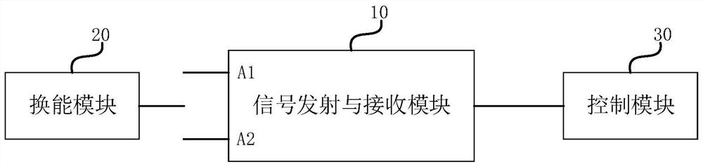
[0039] figure 1 It is a structural block diagram of a flow calculation device provided in Embodiment 1 of the present invention. refer to figure 1 , the flow calculation device includes: a signal transmitting and receiving module 10, a transduction module 20 and a control module 30; wherein, the signal transmitting and receiving module 10 is electrically connected to the control module 30; the signal transmitting and receiving module 10 includes a signal transmitting terminal A1 and Signal receiving end A2;
[0040] The control module 30 is used to control the conduction between the transduction module 20 and the signal receiving end A2, and simultaneously control the disconnection of the transduction module 20 and the signal transmitting end A1, so as to measure the noise information of the medium to be tested and obtain the noise component; the control module 30 also uses The control transduction module 20 is connected with the signal transmitting end A1 and the signal rec...
Embodiment 2
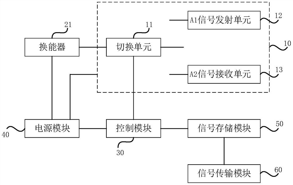
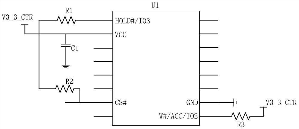
[0050] figure 2 is a schematic structural diagram of a flow calculation device provided in Embodiment 2 of the present invention, image 3 is a schematic diagram of the circuit structure of the signal storage module provided in Embodiment 2 of the present invention, Figure 4 It is a schematic diagram of the current structure of wired communication provided in Embodiment 2 of the present invention, Figure 5 It is a schematic diagram of the current structure of the wireless communication provided in Embodiment 2 of the present invention. On the basis of the first embodiment above, refer to figure 2 , the signal transmitting and receiving module 10 comprises a switching unit 11, a signal transmitting unit 12 and a signal receiving unit 13, the signal transmitting unit 12 comprises a signal transmitting terminal A1, the signal receiving unit 13 comprises a signal receiving terminal A2, the switching unit 11 is connected with the transduction module respectively 20. The sign...
Embodiment 3
[0062] Image 6 It is a schematic structural diagram of a flow calculation device provided in Embodiment 3 of the present invention. On the basis of the above embodiments, optionally, refer to Image 6 , the transducer module includes a first transducer 22 and a second transducer 23, both of the first transducer 22 and the second transducer 23 are connected to the switching unit 11, and the switching unit 11 is used to conduct or disconnect the first transducer A path between a transducer 22 and the signal transmitting unit 12, a path between the first transducer 22 and the signal receiving unit 13, a path between the second transducer 23 and the signal transmitting unit 12, and a path between the second transducer 23 and the signal receiving unit Access to unit 13.
[0063] Wherein, both the first transducer 22 and the second transducer 23 may be ultrasonic transducers.
[0064] Specifically, in the technical solution of this embodiment, refer to Image 6 , the implementa...
PUM
 Abstract
Description
Claims
Application Information
 - R&D Engineer
- R&D Manager
- IP Professional
- Industry Leading Data Capabilities
- Powerful AI technology
- Patent DNA Extraction
Browse by: Latest US Patents, China's latest patents, Technical Efficacy Thesaurus, Application Domain, Technology Topic, Popular Technical Reports.
© 2024 PatSnap. All rights reserved.Legal|Privacy policy|Modern Slavery Act Transparency Statement|Sitemap|About US| Contact US: help@patsnap.com