Pressure drop flow testing system and method for testing pipeline flame arrester

A technology of flow test and flow test device, which is applied in the field of flame arrester performance test, can solve the problems of large error, inability to control the maximum value of pressure, complicated process, etc.

Active Publication Date: 2021-04-09
CHINA PETROLEUM & CHEM CORP +1
View PDF6 Cites 0 Cited by
  • Summary
  • Abstract
  • Description
  • Claims
  • Application Information

AI Technical Summary

Problems solved by technology

[0002] The existing flame arrester pressure drop flow system cannot adjust the value of the pressure drop flow, and can only measure the pressure immediately after the pressure is released from a larger pressure storage space through the pipeline flame arrester
There are many inconveniences: 1. The pressure cannot be controlled to reach the maximum value you want to choose; 2. The pressure cannot be adjusted, and the pressure can only be read quickly while the pressure is falling, and the error is large; 3. The pressure storage space is relatively demanding. High, because the larger the diameter of the flame arrester, the larger the pressure drop required to measure, the higher the pressure requirement of the pressure storage space, this will easily cause safety hazards; 4. Each position needs to be equipped with fixed personnel to read data, The process is complex and prone to errors

Method used


Image

  • Pressure drop flow testing system and method for testing pipeline flame arrester

Examples


Embodiment 1

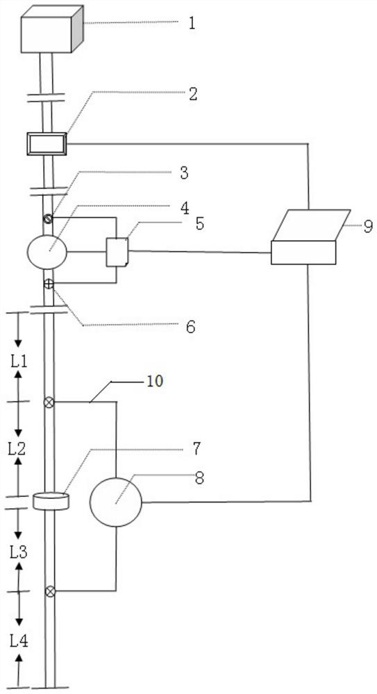
[0031] Such as figure 1 As shown, a pressure drop flow test system for pipeline flame arrester testing, including an air supply device 1, a pressure control device, a pressure drop flow test device and a controller, an air supply device 1, a pressure control device and a pressure drop flow test The devices are connected sequentially. The air supply device 1 can be an air compressor or a fan, and is mainly used to directly provide air for the system, cancel the pressure storage space, and reduce potential safety hazards; the controller is a computer 9,

[0032] The pressure control device includes an electronic pressure controller 2 , a pressure transmitter 3 , a flow meter 4 , an integrator 5 , and a thermocouple 6 . The pressure drop flow test device includes pipeline flame arrester 7 and electronic pressure gauge 8, air supply device 1, electronic pressure controller 2, pressure transmitter 3, flow meter 4, and pipeline flame arrester 7 are sequentially connected through pi...

Embodiment 2

[0037] This embodiment provides a method for testing a pressure drop flow test system for a pipeline flame arrester, which is performed using the pressure drop flow test system described in Embodiment 1, including the following steps:

[0038] (1) Open the air supply device 1 to deliver air with pressure in the pipeline;

[0039] (2) Regulate the electronic pressure controller 2 through the computer 9, adjust the gas pressure through the electronic pressure controller 2, and provide air with a stable pressure for the follow-up pipeline, that is, the pressure of the connected pipeline after the electronic pressure controller 2 can be controlled by the electronic pressure controller 2 control, regulated by computer 9;

[0040] (3) The data measured by the air in the pipeline through the pressure transmitter 3, the flowmeter 4, and the thermocouple 6 are converted at the calculator 5, and finally the flow result under the standard condition is fed back to the computer 9, which ca...

Embodiment 3

[0045] Take the pressure drop flow test of a pipeline flame arrester with a nominal diameter of DN50 as an example:


PUM


Abstract

The invention discloses a pressure drop flow testing system and method for testing a pipeline flame arrester, and belongs to the technical field of flame arrester performance testing; the pressure drop flow testing system comprises an air supply device, a pressure control device, a pressure drop flow testing device and a controller, wherein the air supply device, the pressure control device and the pressure drop flow testing device are connected in sequence. According to the invention, the pressure drop flow test in the mass standard is realized, the stability is kept at different pressure drop numerical points, the pressure drop parameters can be manually adjusted through the controller; meanwhile, the corresponding flow is read, and the measurement error is reduced.

Description

technical field [0001] The invention belongs to the technical field of flame arrester performance testing, in particular to a pressure drop flow testing system and method for pipeline flame arrester testing. Background technique [0002] The flame arrester pressure drop flow rate system in the prior art cannot adjust the value of the pressure drop flow rate, and can only measure the pressure immediately after releasing the pressure from a relatively large pressure storage space through the pipeline flame arrester. There are many inconveniences: 1. Can't control the pressure to reach the maximum value you want to choose; 2. Can't adjust the size of the pressure, you can only take a quick reading when the pressure is falling, and the error is large; 3. The pressure storage space is more demanding High, because the larger the diameter of the flame arrester, the greater the pressure drop required to measure, the higher the pressure demand of the pressure storage space, this will...

Claims


Application Information

Patent Timeline
Patent Type & Authority Applications(China)
IPC IPC(8): G01M13/00
CPCG01M13/00Y02E30/30
Inventor 李厚达鲍磊王鹏于安峰党文义张云燕
Owner CHINA PETROLEUM & CHEM CORP
Why Eureka
Try Eureka