
LED lamp tube with protection function

A technology for LED lamps and protection functions, applied in the field of LED lamps with protection functions, can solve problems such as damage to LED lamps, poor protection effect, easy to cause electric shock, etc., and achieve stable installation and good waterproof protection effect.

Inactive Publication Date: 2021-05-28
戚红艳
View PDF0 Cites 0 Cited by
  • Summary
  • Abstract
  • Description
  • Claims
  • Application Information

AI Technical Summary

Problems solved by technology

[0003] The LED lamp tube is used with electricity inside, but the waterproof effect of the existing LED lamp tube is not good, and it is easy to cause the danger of electric shock when exposed to water. Most of the tubes are made of fragile glass. Once the glass is dropped and splashed, the LED tube will be damaged to a certain extent, and the protection effect is not good.

Method used


Image

  • LED lamp tube with protection function
  • LED lamp tube with protection function
  • LED lamp tube with protection function

Examples


Embodiment 1

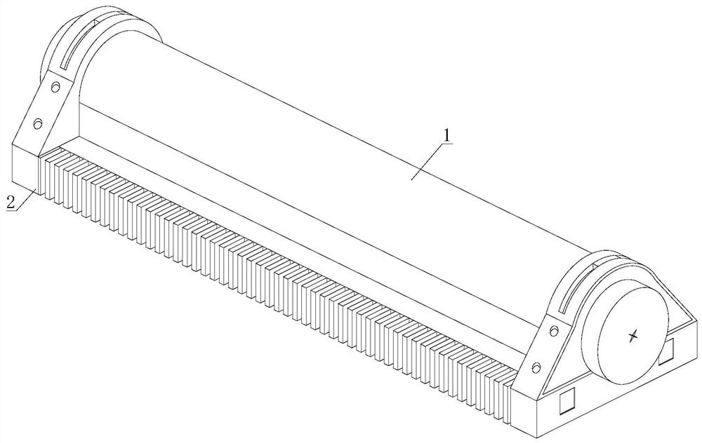
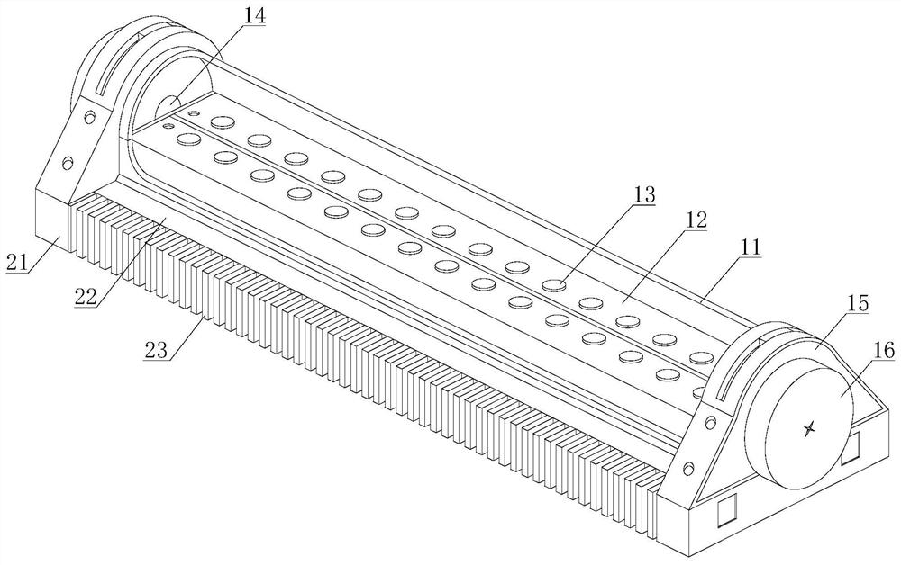
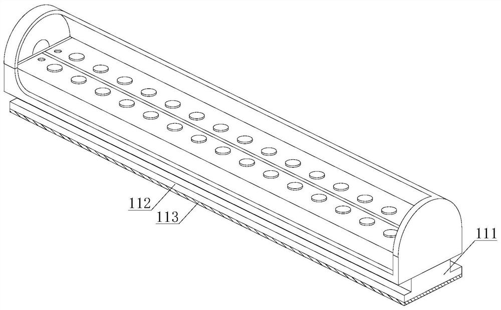
[0032] refer to figure 1 and figure 2 , a LED lamp tube with protective function, including a lamp tube assembly 1 and a base assembly 2, the lamp tube assembly 1 is installed on the upper end of the base assembly 2, the lamp tube assembly 1 includes an outer cover 11, a lamp holder 12, a lamp bead 13, an installation Part 14, protective block 15 and protective mechanism 16, lamp holder 12 is installed inside the outer cover 11, several groups of lamp beads 13 are arranged, and all of them are processed on the upper surface of lamp holder 12, and mounting parts 14 are installed on both sides of lamp holder 12. end, the protective block 15 is installed on the two ends of the outer cover 11, and one end of the protective mechanism 16 is arranged on the outer surface of the protective block 15; the base assembly 2 includes a side plate 21, a stable seat 22 and a rubber waterproof strip 23, and the side plate 21 is fixedly installed on the The two ends of firm seat 22, rubber wa...

Embodiment 2

[0038] refer to figure 1 and figure 2 , a LED lamp tube with protective function, including a lamp tube assembly 1 and a base assembly 2, the lamp tube assembly 1 is installed on the upper end of the base assembly 2, the lamp tube assembly 1 includes an outer cover 11, a lamp holder 12, a lamp bead 13, an installation Part 14, protective block 15 and protective mechanism 16, lamp holder 12 is installed inside the outer cover 11, several groups of lamp beads 13 are arranged, and all of them are processed on the upper surface of lamp holder 12, and mounting parts 14 are installed on both sides of lamp holder 12. end, the protective block 15 is installed on the two ends of the outer cover 11, and one end of the protective mechanism 16 is arranged on the outer surface of the protective block 15; the base assembly 2 includes a side plate 21, a stable seat 22 and a rubber waterproof strip 23, and the side plate 21 is fixedly installed on the The two ends of firm seat 22, rubber wa...


PUM


Abstract

The invention discloses an LED lamp tube with a protection function. The LED lamp tube comprises a lamp tube assembly and a base assembly. In the installation process, when the LED lamp tube inclines towards one side, a sliding block inclines towards one side along a sliding rod, a second spring can be extruded in the process, the sliding rod is subjected to gravity to enable an abutting block to extrude a second air bag, the second air bag is extruded out of the outer end of an inner cavity, the second air bag is filled with nitrogen gas, the density of the nitrogen gas is smaller than that of air, the downwards-inclined end can be lifted upwards, the angle of the LED lamp tube can be quickly recovered, the LED lamp tube can be kept horizontal conveniently, meanwhile, the nitrogen gas is inert gas, the structure is stable, the LED lamp tube can be prevented from generating electric arcs, when the inclination angle of the LED lamp tube is too large to one side, the second air bag slides out of the outer end of the inner cavity, the LED lamp tube can be prevented from impacting the ground, the buffering effect is conveniently achieved, when the LED lamp tube restores to the original position, nitrogen gas in the second air bag can enter the second air bag at the other end through a ventilation pipe, and uniform distribution of the nitrogen gas is conveniently kept.

Description

technical field [0001] The invention relates to the technical field of LED lamp tubes, in particular to an LED lamp tube with protection function. Background technique [0002] Lamp tubes usually refer to straight tube fluorescent lamps. Due to the particularity of the vocabulary, they now refer to lamps with long tubes in appearance. LED lamp tubes refer to lamp tubes that use LEDs as light sources. Compared with fluorescent tubes, they are more energy-saving, cheaper, longer life, It has a simple structure and is a good substitute for future fluorescent tubes. The terminal voltage of the PN junction forms a certain potential barrier. When a forward bias voltage is applied, the potential barrier drops, and the majority carriers in the P and N regions diffuse to each other. Since the mobility of electrons is much greater than that of holes, a large number of electrons will diffuse to the P region, which constitutes the injection of minority carriers into the P region. These...

Claims


Application Information

Patent Timeline
IPC IPC(8): F21K9/27F21V21/00F21V31/00F21V15/04F21Y115/10
CPCF21V15/04F21V21/00F21V31/00F21V31/005F21K9/27F21Y2115/10
Inventor 戚红艳
Owner 戚红艳
Learn More