
Device for writing to or reading from optical recording media

A technology of optical recording media and equipment, applied in the direction of optical recording head, recording/reproducing by optical method, data recording, etc.

Inactive Publication Date: 2003-11-19
DEUTSCHE THOMSON-BRANDT GMBH
View PDF0 Cites 0 Cited by
  • Summary
  • Abstract
  • Description
  • Claims
  • Application Information

AI Technical Summary

Problems solved by technology

[0003] A disadvantage of this known device is that determining the image signal requires the use of multiple analog components, which are subject to tolerances and therefore have to be assembled and adjusted to each other
During the normal operation of the device, such as changing the reflectivity of the optical recording medium to be read and written, its eccentricity, etc., the error sources generated can only be compensated to a limited extent

Method used


Image

  • Device for writing to or reading from optical recording media
  • Device for writing to or reading from optical recording media
  • Device for writing to or reading from optical recording media

Examples


Embodiment Construction

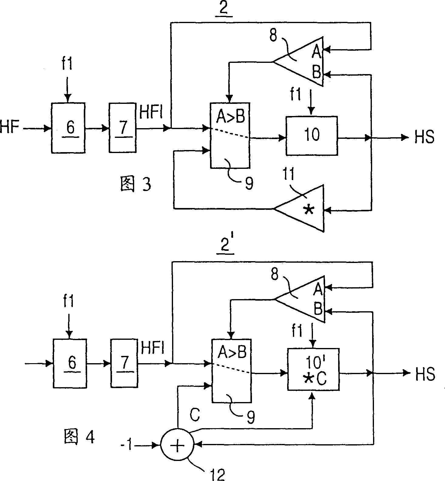
[0024] figure 1 A block diagram of a device according to the invention is shown. In this case, the analog signal HF from the detection means of the device and modulated according to the information stored on the optical recording medium is sent to the track detector 1 which emits a mirror signal M and a fault signal D. The track detector 1 has an envelope detector 2, the output signal of which, the envelope signal HS, is sent to a comparator unit 3, the output signal of which is the mirror signal M. The other input of the comparator unit 3 is connected to the output of an adaptive reference value transmitter 4, the mirror signal M being supplied to its input. The track detector 1 is additionally provided with a flaw detector 5 which generates a fault signal D as a function of the input signal. In the preferred embodiment, the track detector 1 operates on a digital basis, whereby the analog, modulated signal HF is first digitized by an analog-to-digital converter 6 and invert...


PUM


Abstract

The present invention relates to a device for writing to or reading from optical recording media (AT) which have data tracks for recording or reading out information. It has a scanning means for scanning the data tracks, a detection means which emits a signal (HF) which is modulated in accordance with the information stored on the optical recording medium (AT) and a track detector (1), which generates a mirror signal (M) by means of a reference value transmitter which mirror signal indicates whether the scanning means is scanning a data track or the region between two tracks. The object of the present invention is to propose a device of the abovementioned type which is capable of forming a reliable mirror signal without a high outlay. For this purpose, according to the invention, the reference value transmitter (4) is designed as an adaptive reference value transmitter to which the mirror signal (M) us fed as input variable. The invention can be applied to CD, CD-ROM, CR-R, DVD or the like.

Description

technical field [0001] The invention relates to a writing or reading device for optical recording media having a track detector which generates a mirror signal indicating whether a data track or an area between two data tracks is being scanned. Background technique [0002] Known equipment is equipped with for example IC CXA1081M, see Bernd Rodekurt: "Erfolgreicher CD-player" [successful CD-player], Franzis Verlag Munich, 1994, has a track detector, and the track detector has the function that is used to form modulation signal The device of the upper and lower envelopes. The difference between these envelopes is formed and compared with a reference value by a comparator. If the difference is below the reference value, the image signal is set to the value "low", otherwise "high". The reference value is determined from the difference between the envelopes by a fixed predetermined circuit. [0003] A disadvantage of this known device is that determining the image signal requ...

Claims


Application Information

Patent Timeline
IPC IPC(8): G11B7/00G11B7/085G11B7/09G11B7/125
CPCG11B7/08541
Inventor 恩格尔伯特·莱奥弗高木广人
Owner DEUTSCHE THOMSON-BRANDT GMBH
Learn More