Ni-Cr alloy temperature sensor based on magnetostrictive torsional waves

A temperature sensor and magnetostrictive technology, applied in the field of temperature sensors, can solve the problems of low Curie temperature and easy oxidation, and achieve the effects of weak thermal expansion, easy detection, and less energy leakage

Active Publication Date: 2021-05-25
HEBEI UNIV OF TECH
View PDF7 Cites 2 Cited by
  • Summary
  • Abstract
  • Description
  • Claims
  • Application Information

AI Technical Summary

Problems solved by technology

[0005] This invention aims at the problems of poor quality of ultrasonic temperature measurement signal and low Curie temperature of sensitive element material, easy oxidati...

Method used


Image

  • Ni-Cr alloy temperature sensor based on magnetostrictive torsional waves
  • Ni-Cr alloy temperature sensor based on magnetostrictive torsional waves
  • Ni-Cr alloy temperature sensor based on magnetostrictive torsional waves

Examples


Embodiment 1

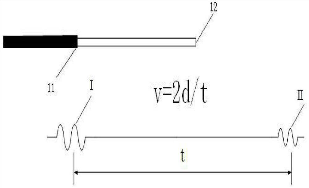
[0073] Example 1: Put the chromium-nickel alloy wire part of the sensor into a high-temperature furnace, heat it at room temperature -1000°C, and detect the change between the two waveforms through the detection coil, and the time difference between the two stress wave peaks is hours delay. The main purpose of this embodiment is to study the relationship between the delay value and the temperature as the temperature rises.

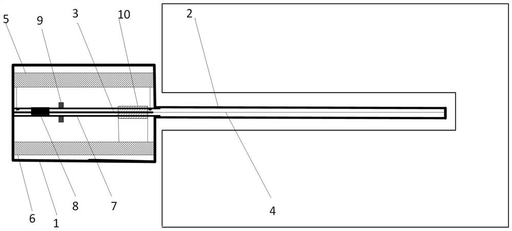
[0074] Experimental platform construction: according to figure 1 The temperature sensor structure shown is installed with various components, and the installed temperature sensor is placed in a high-temperature furnace. As the temperature rises, an oscilloscope is used to observe the output waveform of the detection coil.

[0075] The software or protocols involved in the present invention are all known technologies.

[0076] Experimental process and results: such as Figure 5 As shown, the output voltage curve of the detection coil at 20°C is obtained....

Embodiment 2

[0078] Embodiment 2: use Fe-Ga and a permanent magnet as the torsional wave signal generator, other parts are the same as embodiment 1 in structure, the difference is that the measuring rod is Figure 4 The chromium-nickel alloy wire is flexible and can be bent deep into the measuring rod in the shape of a flat disc. Put the flat measuring rod into a cylindrical high-temperature furnace with a diameter of 240 mm and heat it at room temperature -1000 ° C. Detect changes in the waveform. The main purpose of this embodiment is to verify the reliability of the device signal at high temperature, and to calculate the sound velocity of the torsional wave at different temperatures.

[0079] Experimental platform construction: according to Figure 4 The temperature measuring sensor structure shown is to install various components, and the installed temperature measuring sensor is put into a high temperature furnace. Other steps are the same as in Embodiment 1, and the output waveform ...


PUM

PropertyMeasurementUnit
Lengthaaaaaaaaaa
The maximum diameteraaaaaaaaaa
Lengthaaaaaaaaaa

Abstract

The invention relates to a Ni-Cr alloy temperature sensor based on magnetostrictive torsional waves. The sensor comprises a cylindrical shell, a measuring rod, a Fe-Ga wire, a chromium-nickel alloy wire, a pulse signal generation module, a control sampling module, a ceramic sleeve, a damper, a permanent magnet and a detection coil; the right end of the measuring rod is closed, one end of the chromium-nickel alloy wire is fixed to the center of the inner wall of the right end of the measuring rod, the other end of the chromium-nickel alloy wire penetrates through the measuring rod, enters the shell and is connected with the right end of the Fe-Ga wire at the right portion in the ceramic sleeve, and the left end of the Fe-Ga wire passes through the interior of the ceramic sleeve, penetrates through the damper and is fixed to the center of the inner wall of the left end of the shell; and the appearance of the measuring rod is a linear measuring rod and a planar disc-shaped measuring rod. According to the invention, the noise signal influence caused by high voltage, high frequency and vibration in ultrasonic temperature measurement can be effectively reduced.

Description

technical field [0001] The invention combines the magnetostrictive material with the sensitive element material and applies it to the field of temperature sensors, mainly related to the Fe-Ga filamentary material with magnetostrictive effect and the nickel-chromium alloy wire as the sensitive element material, which can be applied to the temperature sensor. Measurement to realize real-time monitoring of temperature. Background technique [0002] Magnetostrictive temperature sensors have the potential to provide reliable temperature measurement for many applications, including glass and low-melting point metal smelting, process industries, nuclear power plants, etc. where temperature monitoring is critical, enabling real-time temperature monitoring and temperature monitoring of the entire industrial process and The spatial temperature distribution is displayed. There are many problems in thermocouples, thermal resistances and non-contact temperature measurement commonly used...

Claims


Application Information

Patent Timeline
IPC IPC(8): G01K11/24
CPCG01K11/24
Inventor 李明明李保良王千程天宇牛小东
Owner HEBEI UNIV OF TECH
Why Eureka
Try Eureka