Sealed pod propeller

A propeller and pod technology, applied in the field of energy conversion construction machinery, can solve the problems of low energy conversion rate of motors, insufficient water sealing performance, and reduced friction coefficient, etc., achieve strong self-regulation ability, provide energy conversion efficiency, eliminate Effects of Seal Failure

Inactive Publication Date: 2021-05-25
武汉波依迈科技有限公司
View PDF7 Cites 0 Cited by
  • Summary
  • Abstract
  • Description
  • Claims
  • Application Information

AI Technical Summary

Problems solved by technology

[0004] There are usually three driving methods for pod propellers, which are direct drive by underwater motor, drive by underwater oil motor, and drive by the prime mover with the power source in the cabin through a spiral bevel gear pair. To ensure that the inside of the pod propeller is free from dust, Water and other impurities enter, and the active parts need to be sealed. As an important part of the supporting shaft, the bearing reduces the friction coefficient during the movement of the rotor and ensures its rotation accuracy, but it is insufficient in water sealing performance, especially during operation. In the process, in order to make up for the shortage, a sealing device is generally added to the outer side of the bearing, and the existing sealing device mostly adopts a contact seal, which has a large friction coefficient, which in turn leads to a low energy conversion rate of the motor, and the friction generates a large amount of harmful heat.

Method used


Image

  • Sealed pod propeller
  • Sealed pod propeller
  • Sealed pod propeller

Examples


Embodiment 1

[0038] Such as Figure 1~6 As shown, a sealed pod propeller includes a housing 1 and a rotating shaft 31, the rotating shaft 31 is movably connected to the front end head 5 and the tail end cover 4 at both ends of the housing through a bearing 6, and is provided by a motor 32 through a transmission gear 29. Power rotation, the motor 32 is the driving device; the output end of the rotating shaft 31 is provided with a propeller 27; the housing 1 is also provided with an air pressure adjustment device, the air pressure adjustment device includes a cylinder 19 and a piston 18, and the cylinder Both ends of the body 19 are provided with openings to communicate the inside of the propeller with the outside atmosphere. The piston 18 is placed in the cylinder body 19 and slides under the action of the internal and external pressure difference to balance the internal and external pressure difference; the outer side of the bearing 6 is provided with a seal Assembly, the sealing assembly ...

Embodiment 2

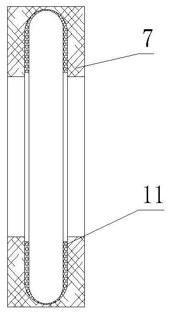
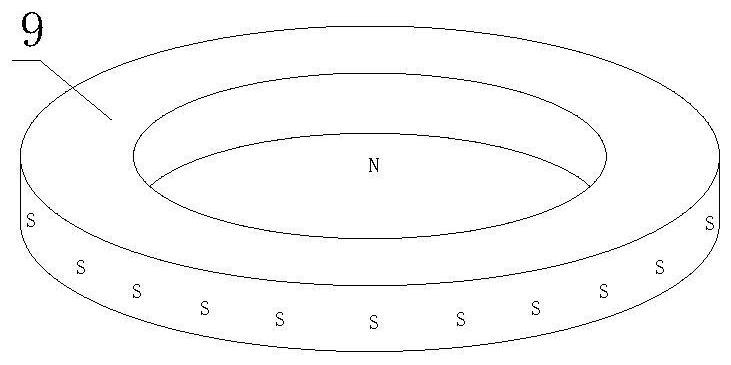
[0042] Such as Figure 7-8 As shown, a sealed pod propeller includes a housing 1 and a rotating shaft 31, the rotating shaft 31 is movably connected to the front end head 5 and the tail end cover 4 at both ends of the housing through a bearing 6, and the motor rotor 3 and the motor stator 2 Power rotation is provided, the rotor 3 is fixed on the rotating shaft 31, the stator 2 provides a radially rotating magnetic field for the rotor 3, and the driving device is a combination of the rotor 3 and the stator 2; the output end of the rotating shaft 31 is provided with a propeller 27; the bearing 6 A sealing assembly is provided on the outside, and the sealing assembly includes a concave pole 7 and a salient pole 8. The concave pole 7 is connected with the permanent magnet 9 and fixed in the end cover; the concave pole 7 is provided with a "U" shape Groove, the concave pole 7 is poured from flexible materials, such as silica gel, polytetrafluoroethylene, etc.; the salient pole 8 is...

Embodiment 3

[0045] Such as Figures 9 to 12As shown, a sealed pod propeller includes a housing 1 and a rotating shaft 31, the rotating shaft 31 is movably connected to the front end head 5 and the tail end cover 4 at both ends of the housing through a bearing 6, and the driving device is an original in the cabin. The motor drives the rotating shaft 31 to rotate through the transmission shaft 30 and the rotating gear; the tail end cover 4 is fixedly connected with the shroud 28; the outer side of the bearing 6 is provided with a sealing assembly, and the sealing assembly includes a concave pole 7 and The salient pole 8, the concave pole 7, the permanent magnet 9 and the exciter 23 are sequentially connected from the inside to the outside and fixed in the cage 20, and the cage 20 is fixedly installed in the installation groove of the end cover; the concave pole 7 is provided with a "U"-shaped groove, and the concave pole 7 is cast from a flexible material, such as silica gel, polytetrafluor...


PUM


Abstract

The invention discloses a sealed pod propeller comprising a shell and a rotating shaft, the rotating shaft is movably connected into end covers on the two sides of the shell through bearings, a driving device installed in the shell provides power for rotation, a propeller is fixedly installed at the output end of the rotating shaft, and a sealing assembly is arranged on the side edge of a bearing; the sealing assembly comprises a concave pole and a convex pole, and one of the concave pole and the convex pole is fixed on the rotating shaft; the concave pole has an annular structure; the outer side of the concave pole is provided with a permanent magnet, and the inner side of the concave pole is provided with a groove; the top of the convex pole is arranged in the groove, and a U-shaped or V-shaped gap is formed between the convex pole pole and the groove; the gap is filled with magnetic fluid; the magnetic fluid is accumulated at the bottom of the groove under the action of a magnetic field provided by the magnetic pole on the inner side of the permanent magnet, and a U-shaped or V-shaped sealing belt is formed between the convex pole pole and the concave pole by utilizing the principle that the fluid is in static pressure balance in the U-shaped pipe. The invention provides a high-performance sealed pod propeller which is good in sealing performance and low in friction coefficient by utilizing magnetofluid sealing.

Description

technical field [0001] The invention belongs to the field of energy conversion engineering machinery, in particular to a sealed pod propeller with good sealing performance and low friction coefficient. [0002] technical background [0003] The pod propeller is an advanced large-scale ship propulsion device. During the driving process, it can not only avoid the propeller from working in the complex turbulent flow of the stern, improve the propulsion efficiency of the ship, save energy and reduce emissions, but also significantly improve the ship's operational performance. If necessary, it can even turn the ship in situ, and can turn horizontally within 360° to achieve vector propulsion. Generally, it is mainly composed of a built-in drive module, a propeller module, a horizontal rotation mechanism and a cooling device. [0004] There are usually three driving methods for pod propellers, which are direct drive by underwater motor, drive by underwater oil motor, and drive by th...

Claims


Application Information

Patent Timeline
Patent Type & Authority Applications(China)
IPC IPC(8): B63H1/14B63H21/17F16J15/43
CPCB63H1/14B63H21/17F16J15/43
Inventor 王前进
Owner 武汉波依迈科技有限公司
Why Eureka
Try Eureka