Quick mounting structure for steel structure

A technology of steel structure and connection device, which is applied in the direction of building structure and construction, and can solve problems such as deformation, large connection error between the main beam and the secondary beam, and deflection of the main beam, so as to ensure the construction time and the connection structure is simple , clear force transmission effect

Pending Publication Date: 2018-11-06
ZHEJIANG FEIWU ARCHITECTURAL TECH CO LTD +1
View PDF9 Cites 0 Cited by
  • Summary
  • Abstract
  • Description
  • Claims
  • Application Information

AI Technical Summary

Problems solved by technology

When the two are applied to the connection between the main beam and the secondary beam, the main beam is supported on two structural columns. Since the main beam has a long span, the self-weight of the main beam can be simplified as a uniform load along its length , resulting in deflection in the mid-span of the main girder; at the same time, because the main girder needs to be hoisted during the installation process, it is easy to produce a certain deformation during the hoisting process, resulting in a large connection error between the main girder and the secondary girder in the later period

Method used


Image

  • Quick mounting structure for steel structure
  • Quick mounting structure for steel structure
  • Quick mounting structure for steel structure

Examples


Embodiment approach

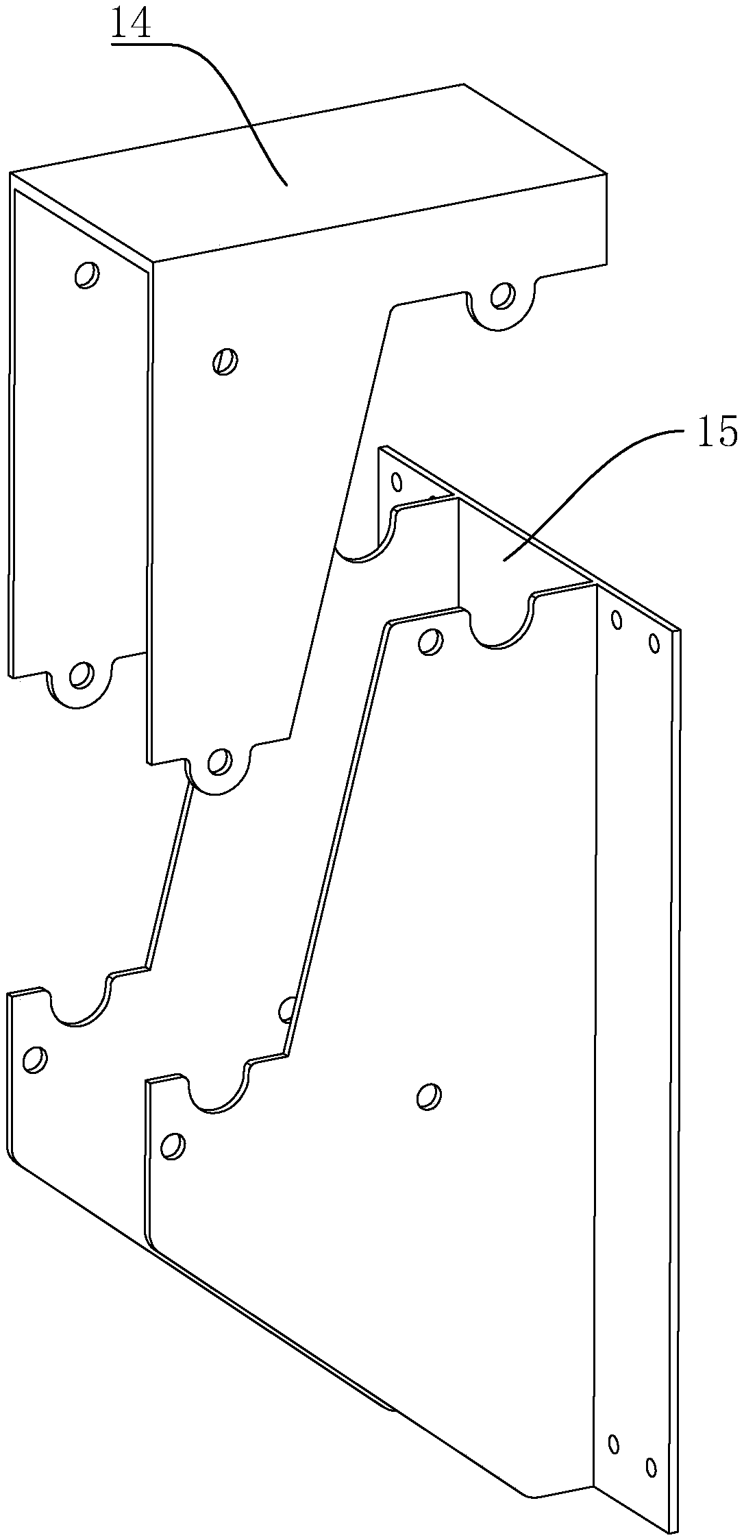
[0047] Another preferred embodiment: the difference from the first preferred embodiment is that, as image 3 As shown, the side of the two support plates 4 facing away from the lug 9 is integrally connected with a side plate 14 , and the side plate 14 and the lug 9 are in the same plane; the tops of the two connecting plates 3 are integrally connected with a top plate 15 . After providing the supporting plate 4 and the connecting plate 3 integrally arranged, the relative width between the two supporting plates 4 is determined, and the position control is more precise.


PUM


Abstract

The invention discloses a quick mounting structure for a steel structure, and relates to the field of fabricated steel structures. According to the key points of the technical scheme, the quick mounting structure comprises a main beam, a secondary beam and a beam connecting device, wherein the secondary beam is mounted on the main beam through the beam connecting device in a combined mode; the beam connecting device comprises a supporting plate, connecting plates, a mortise and tenon structure, and a locking structure; the supporting plate is arranged on the main beam and used for forming a mounting space allowing the secondary beam to be embedded; the connecting plates are arranged on the two sides of the secondary beam and used for being matched with the supporting plate in a guiding mode, inclined guiding structures are arranged between the supporting plate and the connecting plates, the secondary beam is vertically embedded in the mounting space formed by the supporting plate, andthe opposite positions of the secondary beam and the main beam are corrected through the inclined guiding structures; after the secondary beam utilizes the inclined guiding structures to be combined with the main beam, the secondary bema is limited on the main beam in the horizontal direction through the mortise and tenon structure; and the opposite positions of the secondary beam and the main beam are locked through the locking structure. The quick mounting structure has the technical effects that 1, through the beam connecting device, it is ensured that the construction time is shortened andmounting precision is high, the connecting structure is simpler, and force transmitting is clear.

Description

technical field [0001] The invention relates to the field of assembled steel structures, in particular to a quick assembly structure of the steel structure. Background technique [0002] At present, the Chinese patent with publication number CN107476436A discloses a steel structure beam-column mortise-and-mortise joint and its installation method. The joint includes a steel pipe column and a steel beam. , the steel beam is provided with an end plate, the end plate is provided with an embedded tenon, the embedded tenon matches the embedded groove, and the embedded tenon is arranged in the embedded groove. The outer dimension of the embedding groove is smaller than the inner dimension, the cross section of the embedding groove is tapered, the outer dimension of the embedding tenon is larger than the inner dimension, the cross section of the embedding tenon is tapered, and the tenon is passed between the end plate and the reinforcing plate. The self-locking connection in the f...

Claims


Application Information

Patent Timeline
Patent Type & Authority Applications(China)
IPC IPC(8): E04B1/24E04B1/58
CPCE04B1/2403E04B2001/2457E04B2001/2415E04B2001/2412
Inventor 吴幼本黄峻黄允磊徐雅辉徐利军黄勤
Owner ZHEJIANG FEIWU ARCHITECTURAL TECH CO LTD
Why Eureka
Try Eureka