
Composite printing machine

A technology for printing machines and printing mechanisms, applied in printing, printing devices and other directions, can solve the problems of low precision printing accuracy and printing quality, unsatisfactory industrial printing application effect, and large equipment volume, etc., to achieve high printing accuracy and overprinting accuracy. , Wide color gamut effect

Pending Publication Date: 2021-05-25
潍坊彩鸿数码科技有限公司
View PDF0 Cites 0 Cited by
  • Summary
  • Abstract
  • Description
  • Claims
  • Application Information

AI Technical Summary

Problems solved by technology

[0002] There are a variety of printing methods in the printing and packaging industry, including flexo printing, gravure printing, offset printing and digital printing. Flexo printing, gravure printing, and offset printing are all unit-type printing, which have great advantages in printing large color blocks and background colors. It has the advantages of low cost, high efficiency, and no difference, but there are certain deficiencies in overprinting, gradient color, and dot printing. The existing digital printing technologies are mostly plane scanning printing and small roll-to-roll printing. Industrial printing The application effect is not ideal, and small roll-to-roll printing is mainly used in the printing industry, with low speed and narrow format
[0003] Now for the printing of large-format and rich-color packages, unit printing is mainly used. After printing one color layout, it is dried and then printed with other color layouts. Several colors need to be printed several times. The process is cumbersome, the equipment is bulky, and there are problems of fine printing accuracy and low printing quality for overprinting, gradient color and dot printing

Method used


Image

  • Composite printing machine
  • Composite printing machine
  • Composite printing machine

Examples


Embodiment Construction

[0038] The present invention will be further described below in combination with specific embodiments. Wherein, the accompanying drawings are for illustrative purposes only, and represent only schematic diagrams, rather than physical drawings, and should not be construed as limitations on this patent; in order to better illustrate the embodiments of the present invention, some parts of the accompanying drawings may be omitted, Enlargement or reduction does not represent the size of the actual product; for those skilled in the art, it is understandable that some well-known structures and their descriptions may be omitted in the drawings.

[0039]In the drawings of the embodiments of the present invention, the same or similar symbols correspond to the same or similar components; The orientation or positional relationship indicated by etc. is based on the orientation or positional relationship shown in the drawings, and is only for the convenience of describing the present invent...


PUM


Abstract

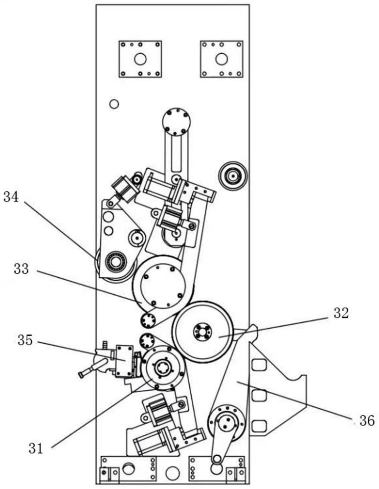
The invention belongs to the technical field of printing, and particularly relates to a composite printing machine. The machine comprises an unwinding unit, a base material receiving unit, a unit printing mechanism, a digital printing mechanism, a unit gloss oil applying mechanism and a winding unit which are sequentially arranged. The digital printing mechanism comprises a jet printing rack, a jet printing roller and a pressing roller are rotatably mounted on the jet printing rack, and a jet printing assembly is arranged at the position, located above the jet printing roller, of the jet printing rack. According to the composite printing machine, spot color printing is conducted on a printing base material through the unit printing mechanism, digital printing is conducted on the printing base material through the digital printing mechanism, the printing base material is wound around the jet printing roller for ink jet printing in the digital printing process, and the printing base material is good in conveying stability and high in printing precision and is matched with the unit printing mechanism to achieve complementary advantages; and wide-width high-speed full-color printing of the printing base material is achieved, the width of the base material can exceed 1 m, and the conveying speed of the base material is high and exceeds 100 m / min.

Description

technical field [0001] The invention belongs to the technical field of printing, and in particular relates to a composite printing machine. Background technique [0002] There are a variety of printing methods in the printing and packaging industry, including flexo printing, gravure printing, offset printing and digital printing. Flexo printing, gravure printing, and offset printing are all unit-type printing, which have great advantages in printing large color blocks and background colors. It has the advantages of low cost, high efficiency, and no difference, but there are certain deficiencies in overprinting, gradient color, and dot printing. The existing digital printing technologies are mostly plane scanning printing and small roll-to-roll printing. Industrial printing The application effect is not ideal, and small roll-to-roll printing is mainly used in the printing industry, with low speed and narrow format. [0003] Now for the printing of large-format and rich-color...

Claims


Application Information

Patent Timeline
Patent Type & Authority Applications(China)
IPC IPC(8): B41J2/01B41J11/00B41J2/165B41J2/175B41J2/19
CPCB41J2/01B41J2/16517B41J2/17503B41J2/19B41J11/002
Inventor 孙清涛王吉晖
Owner 潍坊彩鸿数码科技有限公司
Learn More