
Method for manufacturing thin single-sided flexible circuit board

A technology for flexible circuit boards and manufacturing methods, which is applied in the fields of flexible printed circuit boards, printed circuit manufacturing, and printed circuits, and can solve the problems of difficult processing, easy wrinkling, and high product defect rate in subsequent manufacturing processes.

Inactive Publication Date: 2021-05-18
厦门柔性电子研究院有限公司 +1
View PDF3 Cites 2 Cited by
  • Summary
  • Abstract
  • Description
  • Claims
  • Application Information

AI Technical Summary

Problems solved by technology

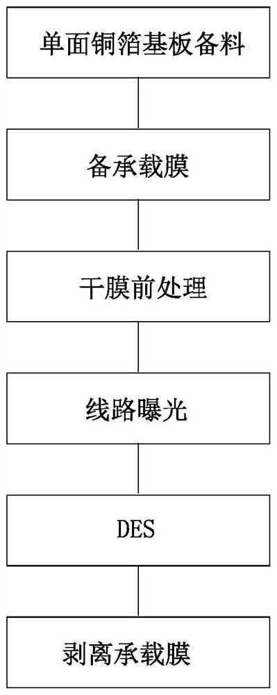
[0002] With the ultra-thin development of portable electronic products, the flexible circuit boards used are getting thinner and thinner. Thin flexible circuit boards are prone to wrinkle defects during the production process. In order to improve product wrinkle defects, such as figure 1 As shown, the existing thin single-sided flexible circuit board adopts a single-sided copper foil substrate that meets the product specifications, and prepares a carrier film on the substrate surface. After the circuit is made, the carrier film is peeled off. It has been improved, but because the expansion and contraction properties of the carrier film and the single-sided copper foil substrate are different, after the carrier film is peeled off, the substrate is curled and bent, and the subsequent process is not easy to process, and after the carrier film is peeled off, the substrate is very thin. It is easy to wrinkle during the manufacturing process, resulting in a high rate of defective products. In the prior art, there is no method that can effectively improve product wrinkled defects. The present invention comes from this

Method used


Image

  • Method for manufacturing thin single-sided flexible circuit board
  • Method for manufacturing thin single-sided flexible circuit board
  • Method for manufacturing thin single-sided flexible circuit board

Examples


Embodiment Construction

[0029] In order to further explain the technical solution of the present invention, the present invention will be described in detail below through specific examples.

[0030] Such as figure 2 Shown, the present invention is a kind of manufacturing method of thin single-sided flexible circuit board, and it comprises the following steps:

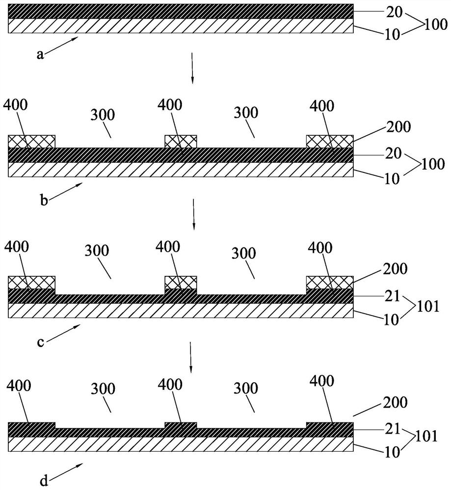
[0031] Step A, single-sided copper foil substrate preparation: prepare single-sided copper foil substrate 100, the thickness of the substrate layer 10 is the same as the thickness of the substrate layer required by the product, and the thickness of the copper layer 20 is thicker than the thickness of the circuit layer of the product, image 3 Middle a is the structural diagram of the single-sided copper foil substrate;

[0032] Step B, drilling positioning holes: drilling positioning holes required for exposure alignment on the single-sided copper foil substrate 100;

[0033] Step C, attaching the dry film: thermally attaching the dry film...


PUM

PropertyMeasurementUnit
Thicknessaaaaaaaaaa

Abstract

The invention discloses a method for manufacturing a thin single-sided flexible circuit board. The method comprises the following steps: A, preparing a single-sided copper foil substrate; B, drilling a positioning hole; C, pasting a dry film; D, performing local exposure; E, performing developing; F, etching thin copper; G, performing demolding; H, performing dry film pretreatment; J, pasting a dry film; K, performing circuit exposure; and L, performing DES. The single-face copper foil substrate is adopted, the thickness of the base material layer of the single-face copper foil substrate is the same as the thickness of the base material layer needed by a product, the thickness of the copper layer of the single-face copper foil substrate is larger than the thickness of the circuit layer of the product, and the product area is developed through the product area local exposure and development technology; and the copper layer in the product area is independently etched and thinned to the thickness of the circuit layer required by the product by adopting a copper etching and thinning process, so that the single-sided copper foil substrates with different required thicknesses are obtained, and the product area meets the product manufacturing requirement.

Description

technical field [0001] The invention relates to the technical field of manufacturing flexible circuit boards, in particular to a method for manufacturing thin single-sided flexible circuit boards. Background technique [0002] With the ultra-thin development of portable electronic products, the flexible circuit boards used are getting thinner and thinner. Thin flexible circuit boards are prone to wrinkle defects during the production process. In order to improve product wrinkle defects, such as figure 1 As shown, the existing thin single-sided flexible circuit board adopts a single-sided copper foil substrate that meets the product specifications, and prepares a carrier film on the substrate surface. After the circuit is made, the carrier film is peeled off. It has been improved, but because the expansion and contraction properties of the carrier film and the single-sided copper foil substrate are different, after the carrier film is peeled off, the substrate is curled and b...

Claims


Application Information

Patent Timeline
IPC IPC(8): H05K3/06
CPCH05K3/064H05K2201/05H05K2203/0369H05K2203/14
Inventor 陈妙芳续振林
Owner 厦门柔性电子研究院有限公司
Learn More