


Quick Research
Generate reliable direction feasibility study reports for your R&D in just a few steps.

Technical Q&A
Discover and master advanced knowledge NOW. Basics, ideas, possibilities, all at once.

Find Solutions
As an expert in R&D theories, this can generate solutions to your technical problems instantly.

Evaluate Feasibility
Analyze your overall solution with one click, know your potential R&D risks in advance.

Monitor Landscape
Get weekly tech updates, stay abreast of the latest tech innovations and key insights.
Novel spherical valve element
A spherical spool, a new type of technology, applied in the direction of valve devices, cocks including cut-off devices, engine components, etc., can solve the problems of poor flow linearity of spherical spools and inability to meet the adjustment flow
- Summary
- Abstract
- Description
- Claims
- Application Information
AI Technical Summary
Problems solved by technology
Method used
Image

Examples
Embodiment Construction
[0020] In order to clearly illustrate the technical features of the solution of the present invention, the solution will be further elaborated below in conjunction with the accompanying drawings and through specific implementation methods.
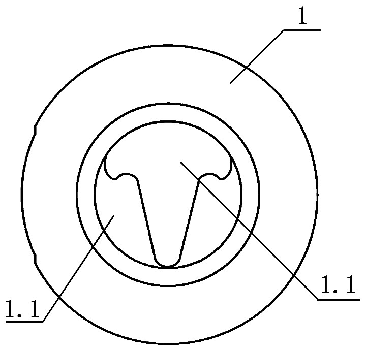
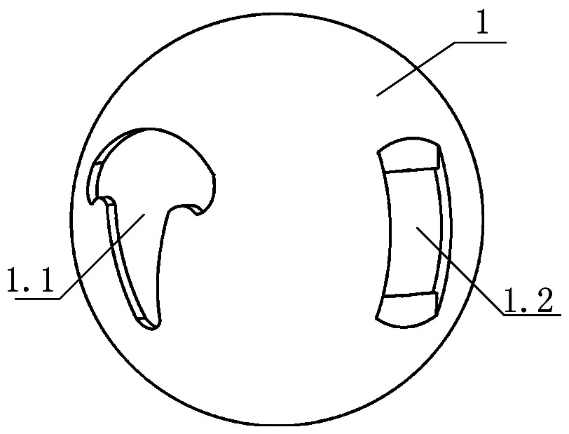
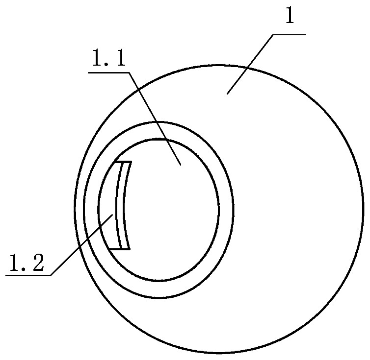
[0021] Such as Figure 1 to Figure 5 As shown in , a new type of spherical valve core is provided, which includes a spherical valve core body 1 as a whole, and the valve core body 1 has a through flow channel 1.1 and a groove 1.2 for installing the valve stem. It has openings at both ends and respectively has a V-like opening structure and a circular opening structure with a semicircular arc-shaped head.
[0022] In this embodiment, the flow channel 1.1 is a spherical hollow structure inside the valve core body 1, the central axis where the valve stem is located perpendicularly intersects the central axis of the flow channel 1.1, and the groove 1.2 and the valve core The flow channel in the body 1 is directly in an impermeable structure, ...
PUM
 Abstract
Description
Claims
Application Information
 - R&D Engineer
- R&D Manager
- IP Professional
- Industry Leading Data Capabilities
- Powerful AI technology
- Patent DNA Extraction
Browse by: Latest US Patents, China's latest patents, Technical Efficacy Thesaurus, Application Domain, Technology Topic, Popular Technical Reports.
© 2024 PatSnap. All rights reserved.Legal|Privacy policy|Modern Slavery Act Transparency Statement|Sitemap|About US| Contact US: help@patsnap.com