Material suction device

A technology of a suction device and a separation device, applied in the field of suction machines, can solve the problems of waste, inability to filter dust, and many impurities in the finished product.

Pending Publication Date: 2021-05-18
广东逢春塑料包装有限公司
View PDF0 Cites 0 Cited by
  • Summary
  • Abstract
  • Description
  • Claims
  • Application Information

AI Technical Summary

Problems solved by technology

[0003] However, in the existing ones, the purchased materials are poured from the packaging bags into the storage tank for later use. The materials are mixed with a large amount of dust and cannot be filtered. When the materials enter the injection molding machine through the suction machine, the injected finished products have too many impurities. Too many defective products cause waste

Method used


Image

  • Material suction device
  • Material suction device
  • Material suction device

Examples


Embodiment 1

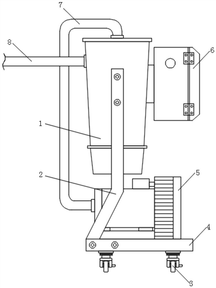
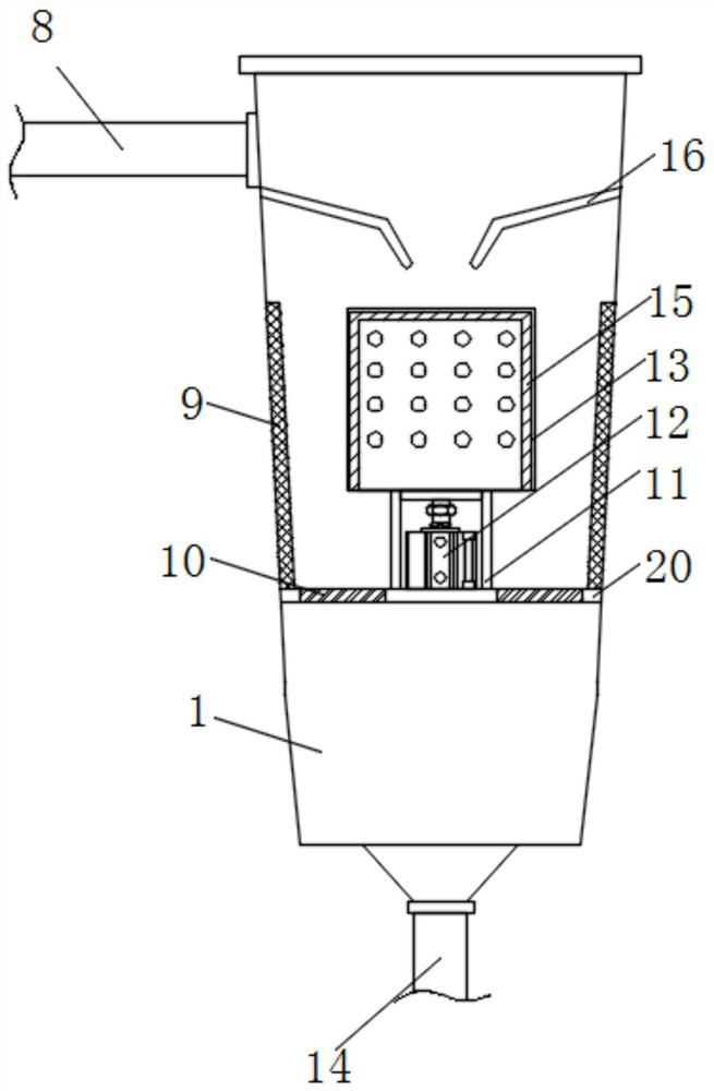
[0028] Now in conjunction with accompanying drawing and specific embodiment the present invention is further described, as Figure 1-3 As shown, the material suction device according to the embodiment of the present invention includes a silo 1, and a support frame 2 is installed on both sides of the silo 1, and a bottom plate 4 is installed at the bottom of the support frame 2, and a passage between the bottom plate 4 and the support frame 2 The screws are fixed, the top of the base plate 4 is installed with a vacuum pump 5, and one side of the vacuum pump 5 is equipped with a gas pipe 7, and the end of the gas pipe 7 far away from the vacuum pump 5 is connected with the feed bin 1, and the feed bin 1 side is installed with a feed pipe 8. A support plate 20 is installed inside the warehouse 1, and a separation device is installed on the top of the support plate 20. The separation device includes a support seat 11, a centrifugal motor 12 is installed inside the support seat 11, ...

Embodiment 2

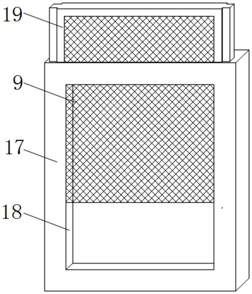
[0031] Such as Figure 1-3 As shown, for the suction device, the side of the feed bin 1 away from the feed pipe 8 is installed with a control box 6, and the control box 6 is connected with the feed bin 1 through an installation block; the bottom plate 4 is far away from the vacuum pump 5 A universal wheel 3 is installed at one end; a slant plate 16 is installed inside the bin 1, and the slant plate 16 is on the top of the separation device; adsorption mechanisms are installed on both sides of the separation device; the adsorption mechanism includes a fixed plate 17, and the middle part of the fixed plate 17 A groove 18 is provided, and a fixed block 19 is installed inside the groove 18, and the fixed block 19 is movably connected with the fixed plate 17, and an electrostatic dust collector 9 is installed inside the fixed block 19.

[0032] Through the above scheme of the present invention, the negative pressure airflow generated by the vacuum pump 5 enters the inside of the si...


PUM


Abstract

The invention discloses a material suction device. The material suction device comprises a material bin, supporting frames are installed on the two sides of the material bin, a bottom plate is installed at the bottom ends of the supporting frames, the bottom plate and the supporting frames are fixed through screws, a vacuum pump is installed at the top end of the bottom plate, an air pipe is installed on one side of the vacuum pump, the end, away from the vacuum pump, of the air pipe is connected with the material bin, a feeding pipe is installed on one side of the material bin, a supporting plate is installed in the material bin, a separating device is installed at the top end of the supporting plate and comprises a supporting seat, and a centrifugal motor is installed in the supporting seat. The environment pollution caused by the fact that dust in materials flies into the air can be effectively reduced, damage to the body health of a user due to the fact that the dust is inhaled into the respiratory tract of the user is avoided, and meanwhile, the waste situation caused by too many defective goods and finished product impurities due to the fact that the materials are not filtered is effectively avoided.

Description

technical field [0001] The invention relates to the technical field of suction machines, in particular to a suction device. Background technique [0002] The suction machine is widely used in the raw material transportation industry of injection molding machines, extruders and other equipment. It has the advantages of convenient installation, simple operation, strong long-distance transportation capacity, stable production, and reliable operation. It is an auxiliary equipment for fully automated production. , The suction machine mostly adopts the way of vacuum suction. The working principle of vacuum suction is to form a certain negative pressure in the hopper cavity to suck the material into the hopper. [0003] However, in the existing ones, the purchased materials are poured from the packaging bag into the storage tank for later use. The materials are mixed with a large amount of dust and cannot be filtered. When the materials enter the injection molding machine through t...

Claims


Application Information

Patent Timeline
IPC IPC(8): B65G53/24B65G53/34B03C7/02B04B3/00B29C45/18B29C48/285
CPCB03C7/02B04B3/00B29C45/18B65G53/24B65G53/34B29C48/288
Inventor 叶春彬
Owner 广东逢春塑料包装有限公司
Why Eureka
Try Eureka