Continuous steel machining device

A technology for processing equipment and steel materials, which is applied in the field of continuous steel processing equipment, and can solve problems such as the inability to realize the discharge of angle steel

Active Publication Date: 2021-05-18
湖州学院
View PDF1 Cites 0 Cited by
  • Summary
  • Abstract
  • Description
  • Claims
  • Application Information

AI Technical Summary

Problems solved by technology

[0004] However, this equipment cannot realize the output of the bent angle steel, and manual subsequent stacking is still required

Method used


Image

  • Continuous steel machining device
  • Continuous steel machining device
  • Continuous steel machining device

Examples


Embodiment

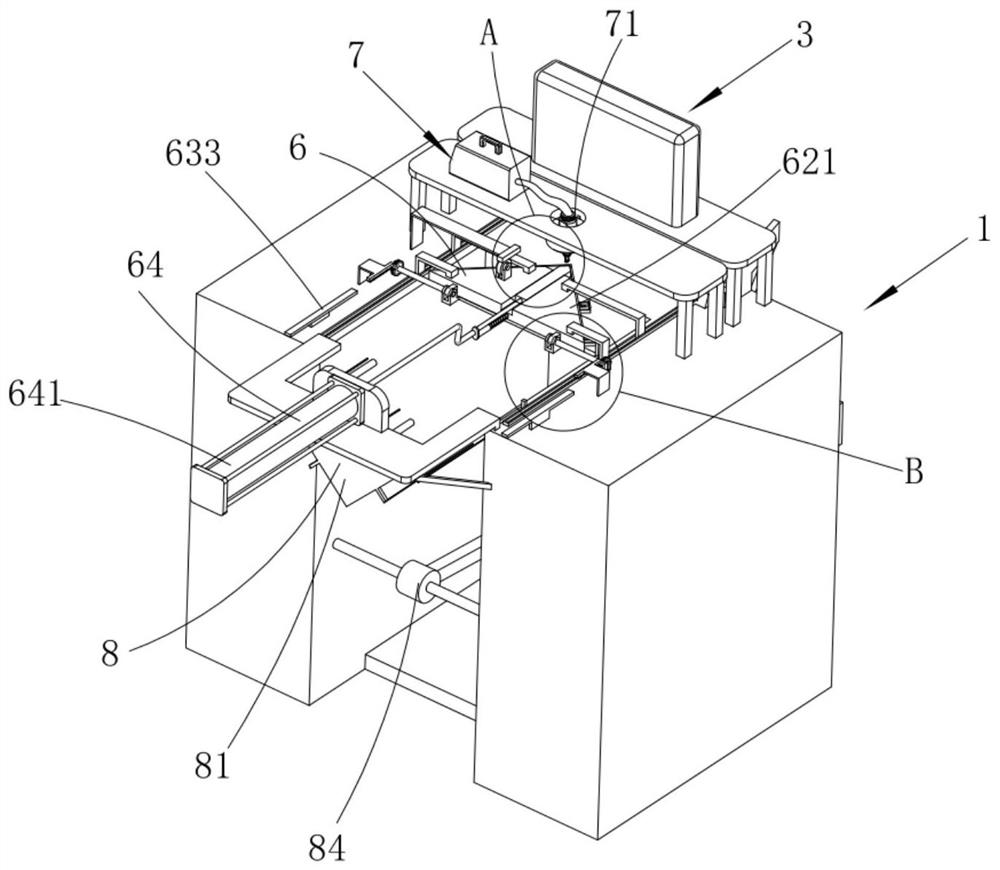
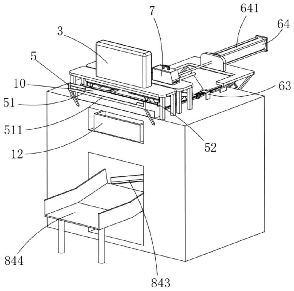
[0047] Such as figure 1 and figure 2 As shown, a continuous processing equipment for steel includes a workbench 1, a lower die 2 installed on the workbench 1, and an upper die 4 that is power-connected with the stamping equipment 3 and is facing the lower die 2. The lower die 2 The bottom is provided with a punching groove 21, and the bottom of the upper die 4 is provided with a punch 41 corresponding to the punching groove 21, and also includes:

[0048] Feeding device 5, said feeding device 5 includes a material shifting assembly 51 arranged on one side of said lower die 2 and a control assembly 52 that drives and connects said dialing assembly 51 and said upper die 4;

[0049] Bending device 6, said bending device 6 includes a mold base 61 that transitionally connects said lower die 2 and said material shifting assembly 51 and a mold base 61 that is slidably arranged on said workbench 1 and correspondingly cooperates with said mold base 61 The die assembly 62, the fasten...


PUM


Abstract

The invention relates to a continuous steel machining device which comprises a workbench, a lower die, an upper die, a feeding device, a bending device, a welding device and a discharging device, the feeding device comprises a shifting assembly and a control assembly, the bending device comprises a die pressing assembly matched with a die holder, a fastening assembly rotatably mounted at the bottom of the die pressing assembly and a driving assembly, the die pressing assembly comprises a mounting seat, an ejector pin assembly and a speed regulating assembly for driving the mounting seat and the ejector pin assembly to move relatively, the fastening assembly comprises a rotating plate rotatably arranged, a limiting plate capable of forming an accommodating groove with the rotating plate and the mounting base, a plurality of limiting assemblies rotatably mounted at the edge of the rotating plate, and a power assembly for driving the rotating plate to rotate, the welding device comprises a welding head assembly, and the discharging device comprises an abutting rod a correspondingly driving the limiting assemblies to rotate, an abutting rod b capable of penetrating through the rotating plate to be abutted against angle steel, and a receiving assembly rotatably mounted below the mounting plate and connected with the mounting base in a power manner. According to the device, continuous machining of the angle steel can be achieved.

Description

technical field [0001] The invention relates to the field of steel processing equipment, in particular to a continuous processing equipment for steel. Background technique [0002] At present, angle steel is widely used in various building structures and engineering structures, such as house beams, pipe supports, bridges, transmission towers, lifting and transportation machinery, ships, industrial furnaces, reaction towers, container frames, cable trench supports, power piping, For the installation of busbar brackets and warehouse shelves, angle steel needs to be bent during use. [0003] The utility model patent with the Chinese patent application number CN201320410929.2 discloses a bending mold used on a multifunctional hydraulic angle steel processing machine, including a bending mold base adapted to the mold placement cavity provided on the mold placement frame, A bending die is fixedly installed on the bending die frame, a bending punch connected with the piston rod of...

Claims


Application Information

Patent Timeline
IPC IPC(8): B21D7/16B21D28/02B21D35/00B21D43/00B23K37/04B23P23/04
CPCB21D28/02B21D35/002B21D7/16B21D43/003B23K37/0426B23P23/04
Inventor 郑慧萌
Owner 湖州学院
Why Eureka
Try Eureka