
Light anti-seismic floor slab connecting joint and using method thereof

A technology for connecting nodes and floors, applied in the directions of floors, shockproof, building components, etc., can solve the problems of poor installation stability, reduced work efficiency, cumbersome installation process, etc., to prevent rebound, ensure stability, and ensure the effect of normal use.

Inactive Publication Date: 2021-08-10
温州富贾科技有限公司
View PDF0 Cites 0 Cited by
  • Summary
  • Abstract
  • Description
  • Claims
  • Application Information

AI Technical Summary

Problems solved by technology

[0004] In view of this, the present invention provides a lightweight anti-seismic floor connection node in order to solve the problems in the prior art that the installation process of the floor connection node is too cumbersome, the installation stability is poor, the work burden of workers is increased, and the work efficiency is also reduced. and how to use it

Method used


Image

  • Light anti-seismic floor slab connecting joint and using method thereof
  • Light anti-seismic floor slab connecting joint and using method thereof
  • Light anti-seismic floor slab connecting joint and using method thereof

Examples


Embodiment 1

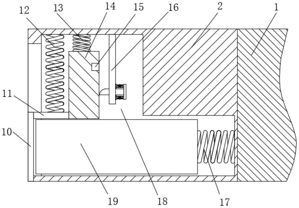
[0043] Such as Figure 1-10 As shown, a light-weight earthquake-resistant floor connection node includes a floor body 1 and a concrete embedded block 6. Both sides of the floor body 1 are fixedly connected with connection boxes 2, and the sides of the two connection boxes 2 that are far away from each other are provided with The second installation groove 18, the two second installation grooves 18 are misplaced, and the inside of the second installation groove 18 is provided with a connection assembly for connecting two floor slab bodies 1, and the inside of the concrete pre-embedded block 6 is provided with a connection hole 3 and The first installation groove 7, the connection hole 3 and the first installation groove 7 are connected, the inside of the first installation groove 7 is provided with a fixing assembly for fixing the connection assembly, and both sides of the concrete embedded block 6 are provided with Z-shaped grooves 24 , the inside of the Z-shaped groove 24 is ...

Embodiment 2

[0052] This embodiment is improved on the basis of Embodiment 1: as Figure 1-10 As shown, including the floor body 1 and the concrete embedded block 6, the two sides of the floor body 1 are fixedly connected with the connection box 2, and the side of the two connection boxes 2 away from each other is provided with a second installation groove 18. The second installation groove 18 is arranged in a misplaced position. The inside of the second installation groove 18 is provided with a connecting assembly for connecting two floor slab bodies 1. The inside of the concrete pre-embedded block 6 is provided with a connecting hole 3 and a first installing groove 7. The connecting hole 3 It communicates with the first installation groove 7, and the inside of the first installation groove 7 is provided with a fixing assembly for fixing the connection assembly. Both sides of the concrete pre-embedded block 6 are provided with Z-shaped grooves 24, and the inside of the Z-shaped groove 24 i...


PUM


Abstract

The invention relates to a light anti-seismic floor slab connecting joint and a using method thereof. The light anti-seismic floor slab connecting joint comprises floor slab bodies and a concrete pre-embedded block, wherein connecting boxes are fixedly connected to the two sides of each floor slab body correspondingly, second mounting grooves are formed in the sides, away from each other, of every two connecting boxes correspondingly, a connecting assembly used for connecting the two floor slab bodies is arranged in each second mounting groove, connecting holes and first mounting grooves are formed in the concrete pre-embedded block, the connecting holes communicate with the first mounting grooves, fixing assemblies used for fixing the connecting assemblies are arranged in the first mounting grooves, and Z-shaped grooves are formed in the two sides of the concrete pre-embedded block correspondingly; limiting assemblies used for limiting the fixing assemblies are arranged in Z-shaped grooves, fixing blocks are fixedly connected to the two sides of the concrete pre-embedded block correspondingly, and the problems that the mounting process of the floor slab connecting joint is too tedious, the mounting stability is poor, the workload of workers is increased, and the working efficiency is further reduced in the prior art are solved.

Description

technical field [0001] The invention belongs to the field of construction, and relates to a connection node of a lightweight anti-seismic floor slab and an application method thereof. Background technique [0002] Prefabricated panels are the floor slabs used in the early 20th century buildings, which are the modules or panels used in the project. Because the prefabricated concrete parts are produced and processed in the prefabrication field, and are directly transported to the construction site for installation, they are called prefabricated panels. When making prefabricated panels, first use wooden boards to nail the hollow model, after distributing steel bars in the hollow part of the model, fill the hollow part with cement, knock off the wooden board after it dries, and the rest is the prefabricated board. Prefabricated panels have many uses in construction, such as the cement panels covered on the ditch next to the road; the cement panels used as the insulation layer o...

Claims


Application Information

Patent Timeline
Patent Type & Authority Applications(China)
IPC IPC(8): E04B5/02E04B1/98E04H9/02E04G21/14
CPCE04B1/98E04B5/023E04G21/14E04H9/021
Inventor 李秋兰倪赐圭
Owner 温州富贾科技有限公司
Learn More