Cement production equipment with dust removal device
A technology for production equipment and dust removal devices, which can be used in combination devices, gas treatment, and dispersed particle separation to solve problems such as air pollution and lung damage.
- Summary
- Abstract
- Description
- Claims
- Application Information
AI Technical Summary
Problems solved by technology
Method used
Image
Examples
Embodiment 1
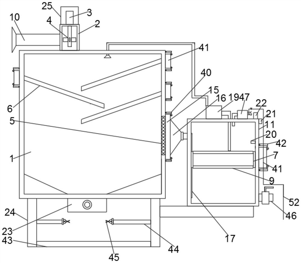
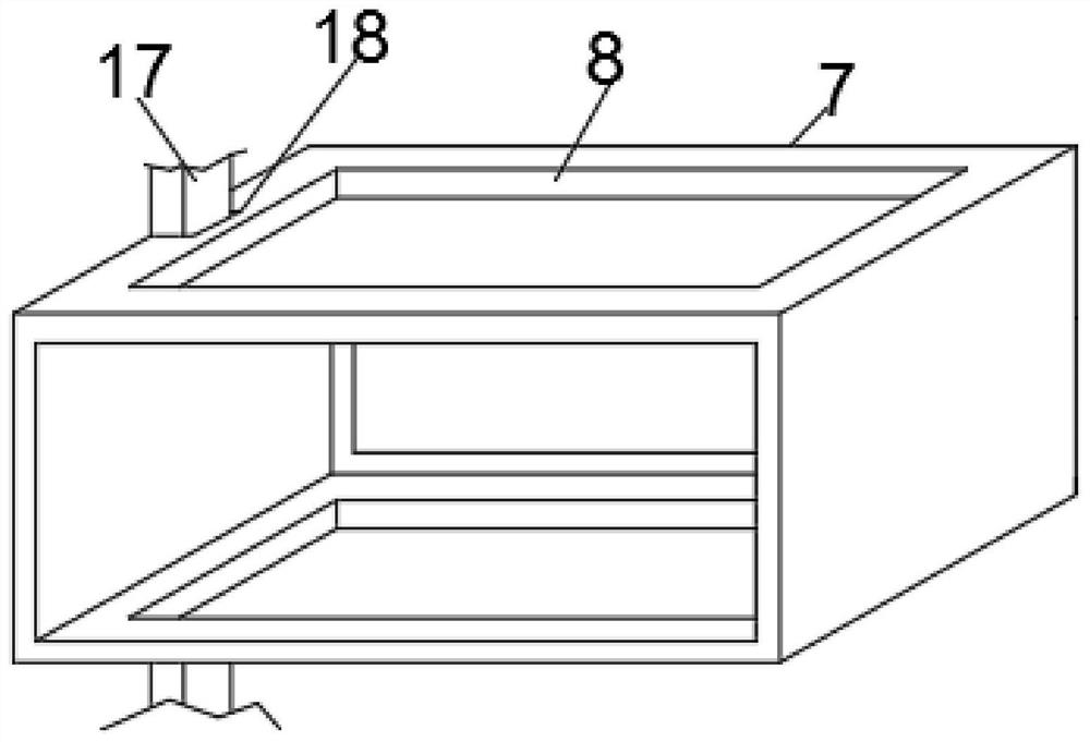
[0033] see Figure 1-5 According to an embodiment of the present invention, a cement production equipment with a dust removal device includes a dust removal box 1, a setting box 2 is arranged on the top of the dust removal box 1, a sound insulation mechanism is arranged on the setting box 2, and the setting box 2 The motor 3 is installed on the top by screws, the output end of the motor 3 is connected to a rotating rod, and the fan blade 4 is installed on the rotating rod, and the rotating rod passes through the setting box 2 and extends to the inside of the setting box 2 , the fan blade 4 is rotated inside the setting box 2, the inside of the dust removal box 1 communicates with the inside of the setting box 2, the sound insulation mechanism acts on the motor 3, and the inner wall of the dust removal box 1 is recessed and installed There is a filter screen 5, a dust shield 6 is installed on the inner wall of the dust removal box 1, a water tank 11 is provided on one side of t...
Embodiment 2
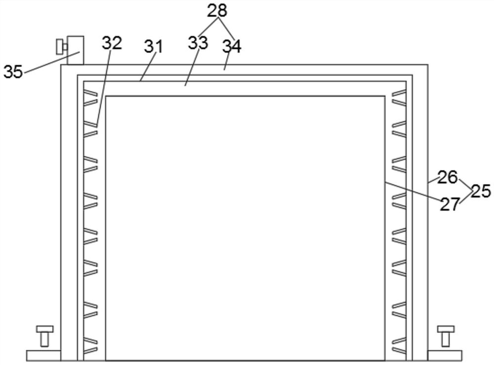
[0035] see image 3 , for the sound insulation mechanism, the sound insulation mechanism is a sound insulation cover 25, and the screws passed by the sound insulation cover 25 are installed on the top of the setting box 2, and the sound insulation cover 25 is set on the motor 3, the The soundproof cover 25 is divided into an outer shell 26 and an inner shell 27, an inner cavity 28 is formed between the inner shell 27 and the outer shell 26, and a sound inlet leading to the inner cavity 28 is opened on the inner shell 27 29. Sound-absorbing cotton 30 is pasted on the inner wall of the sound inlet hole 29, and a sound-insulating board 31 is installed inside the inner cavity 28. A thin metal sheet 32 is surface mounted.
[0036] Through the above scheme of the present invention, the beneficial effect is that the soundproof cover 25 is set on the motor 3, which has a certain protective effect on the motor 3, and the sound generated when the motor 3 is working enters the interio...
Embodiment 3
[0038] see image 3 , for the thin metal sheets 32, the thin metal sheets 32 are arranged obliquely, and the adjacent thin metal sheets 32 are arranged in a figure-eight shape, and the sound insulation board 31 is fixed inside the internal cavity 28 , and the sound insulation board 31 separates the internal cavity 28 into a right sound insulation cavity 33 and a left sound insulation cavity 34, the left sound insulation cavity 34 is injected with water, and the outer surface of the sound insulation cover 25 is provided with a control valve The water inlet pipe 35.
[0039] Through the above scheme of the present invention, the beneficial effect is that the sound insulation board 31 divides the internal cavity 28 into a right sound insulation chamber 33 and a left sound insulation chamber 34, and the right sound insulation chamber 33 is provided with parts such as a sound insulation board 31 and a thin metal sheet 32. Water is injected into the cavity 34, so that the left soun...
PUM
 Abstract
Description
Claims
Application Information
 - R&D
- Intellectual Property
- Life Sciences
- Materials
- Tech Scout
- Unparalleled Data Quality
- Higher Quality Content
- 60% Fewer Hallucinations
Browse by: Latest US Patents, China's latest patents, Technical Efficacy Thesaurus, Application Domain, Technology Topic, Popular Technical Reports.
© 2025 PatSnap. All rights reserved.Legal|Privacy policy|Modern Slavery Act Transparency Statement|Sitemap|About US| Contact US: help@patsnap.com


