Implant cavity measuring rod and method with restoration guidance under tooth tip dislocation as reference

A technique for staggered cusps and implants, which is applied in the field of medical measurement and can solve problems such as obstruction, perforation, and difficulty in taking out.

Pending Publication Date: 2021-05-18
南方医科大学口腔医院
View PDF0 Cites 2 Cited by
  • Summary
  • Abstract
  • Description
  • Claims
  • Application Information

AI Technical Summary

Problems solved by technology

The doctor's clinical experience is a subjective judgment, which is prone to misjudgment and affect the effect of implant placement
[0008] 3. If the patient is ordered to occlude to the ideal occlusal state where the cusps are interlaced, the parallel rod will be squeezed deep into the bone, destroying the cavity structure and affecting the accuracy of the cavity size
At the same time, the strong compression of the parallel rods will cause bone marrow cavity hemorrhage,

Method used


Image

  • Implant cavity measuring rod and method with restoration guidance under tooth tip dislocation as reference
  • Implant cavity measuring rod and method with restoration guidance under tooth tip dislocation as reference
  • Implant cavity measuring rod and method with restoration guidance under tooth tip dislocation as reference

Examples


Embodiment 1

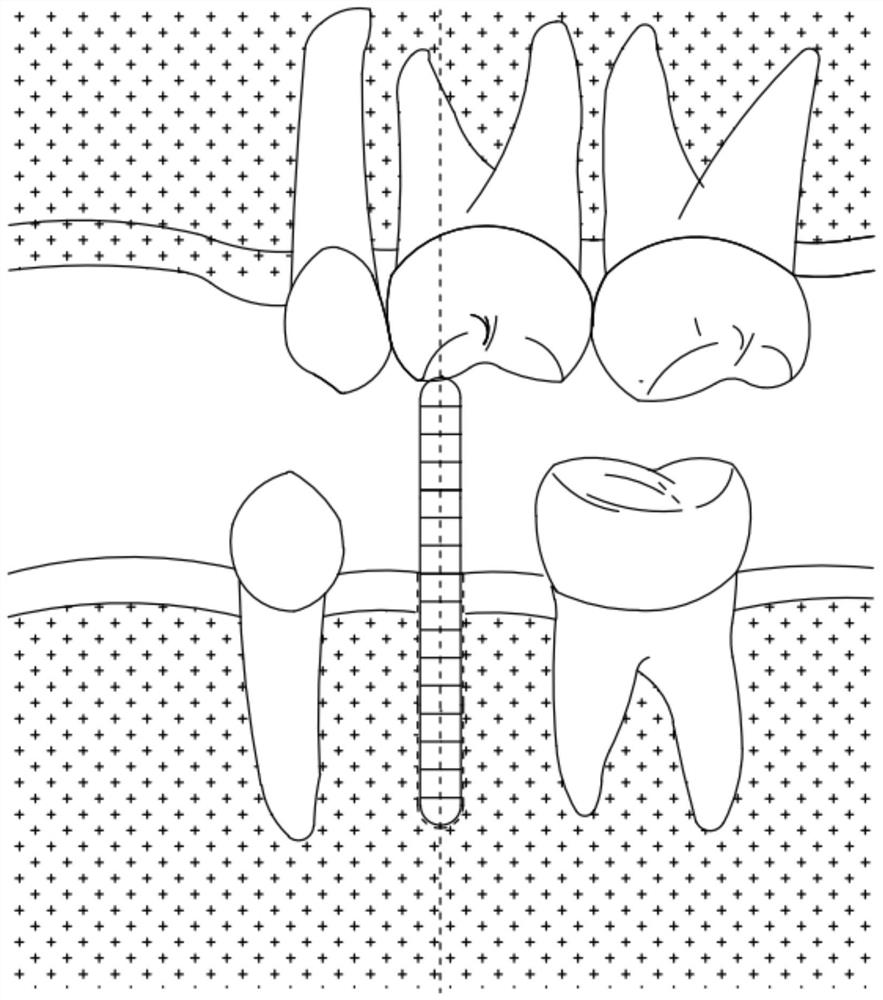
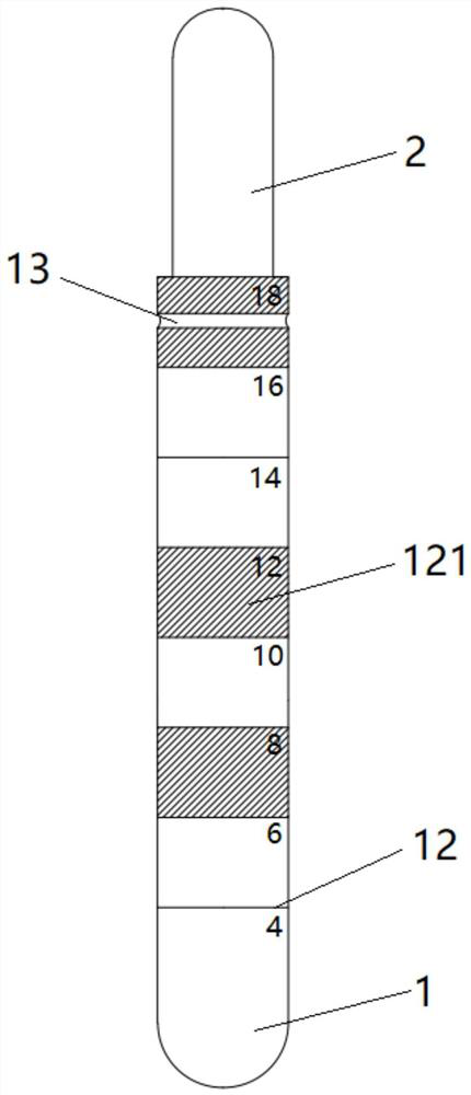
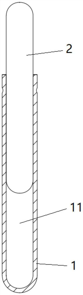
[0053] As shown in Figure 2 and image 3 As shown, this embodiment provides an implant cavity measuring rod based on the prosthetic guide under the cusp staggered position, which is composed of an intraosseous rod 1 and an occlusal rod 2; 2 is inserted into the hollow cavity 11, so that the central axis of the intraosseous rod 1 and the occlusal rod 2 coincide, and the occlusal rod 2 can slide telescopically in the hollow cavity 11.

[0054] Such as Figure 4 and Figure 5 As shown, during use, one end of the occlusal rod 2 is inserted into the hollow cavity 11 of the intraosseous rod 1 to complete the combination of two rod structures to form a complete measuring rod. Then insert the intraosseous rod 1 into the prepared cavity 3 in the patient's edentulous space, and make one end of the intraosseous rod 1 inserted into the cavity 3 abut against the bottom surface of the cavity 3, and the other end protrude from the opening of the cavity 3, occlusal The rod 2 is telescopica...

Embodiment 2

[0063] In order to alleviate the patient's discomfort during the treatment process and reduce the probability of medical accidents in this implementation, the measuring rod scheme provided in Example 1 has been improved in detail as follows:

[0064] The cavity 3 is a circular hole drilled from the surface of the edentulous space into the bone, and the intraosseous rod 1 and the occlusal rod 2 are both cylindrical rod structures.

[0065] The end surface of the occlusal rod 2 in contact with the occlusal surface 41 of the opposing teeth is rounded to form a convex arc surface.

[0066] The end surface of the intraosseous rod 1 embedded in the cavity 3 is rounded to form a convex arc surface

[0067] Such as figure 2 , image 3 , Figure 4 and Figure 5 As shown, the two rods are set as cylindrical rods, and the surfaces of the two rods in contact with the tissue structure are smoothed, and all the edges and corners of the two rods and the transition of the end faces are r...

Embodiment 3

[0073] This example provides a method for measuring the cavity of an implant based on the prosthetic guide under the cusp interlaced position. The measurement rod scheme described in Example 1 or Example 2 is adopted, and the following steps are implemented to plan the gap between the patient's missing teeth. A 4.8mm diameter implant was placed. Such as Figure 4 and Figure 5 shown.

[0074] Step 1: Before the implant surgery, prepare the pioneer drill bit, the reamer drill bit and corresponding matching multiple measuring rods in advance. Among them, there are two types of Pioneer drills with a diameter of 2.2mm and 2.8mm, and two types of reaming drills with a diameter of 3.5mm and 4.2mm. The diameters of the measuring rods corresponding to each drill bit are 2.2mm, 2.8mm, 3.5mm and 4.2mm respectively.

[0075] Step 2: Select a pioneer drill with a diameter of 2.2mm and assemble it on the drilling machine, and drill a hole at the surgical site in the patient's edentulou...


PUM

PropertyMeasurementUnit
Diameteraaaaaaaaaa
Diameteraaaaaaaaaa
Diameteraaaaaaaaaa

Abstract

The invention discloses an implant cavity measuring rod and method with restoration guidance under tooth tip dislocation as reference. The measuring rod comprises an in-bone rod and an occlusion rod, wherein the interior of the in-bone rod is hollow to form a hollow cavity, the occlusion rod is telescopically embedded in the hollow cavity and is in friction fit with the hollow cavity, the occlusion rod and the in-bone rod are coaxially arranged, the in-bone rod is used for being embedded in a cavity and protruding out of a bone surface, the occlusion rod is higher than the occlusion surface of an adjacent tooth and is used for abutting against and making contact with an involution tooth, and the outer wall of the in-bone rod is provided with a scale. The method adopts multiple measuring rods with progressively increased diameters, in the process of gradually expanding the cavity, the cavity is measured once after each time of hole expansion is completed, and the position, depth and axial direction of the cavity and the contact relation between a subsequently implanted implant and the occlusion surface of the involution tooth are obtained with the ideal occlusion state of the tooth tip dislocation of a patient as reference. The long-term aesthetics, biomechanics and occlusion function stability of the patient after the implant is implanted are effectively guaranteed.

Description

technical field [0001] The invention belongs to the technical field of medical measurement, and in particular relates to an implant cavity measuring rod and a method based on the prosthetic guide under the cusp interlaced position. Background technique [0002] Dental implant restoration is widely used in the restoration of patients' missing teeth. Substances that are placed in a patient's mouth to replace missing teeth are called implants or dental implants. Opponents are the natural teeth that occlude with the implants. In the first-stage operation of implant implantation, a cavity is surgically prepared in the alveolar bone of the patient's edentulous position. The position, depth and axial direction of the cavity will affect the occlusal relationship between the implant and the opposing teeth. Therefore, it is necessary to measure the position, depth, and axial direction of the cavity and adjust it in time to ensure that the subsequent implants placed in the cavity and...

Claims


Application Information

Patent Timeline
IPC IPC(8): A61C19/04A61C19/05
CPCA61C19/04A61C19/042A61C19/05
Inventor 周腾飞容明灯
Owner 南方医科大学口腔医院
Why Eureka
Try Eureka