
Display panel, display device and manufacturing method of array substrate

A technology for display panels and array substrates, used in semiconductor/solid-state device manufacturing, semiconductor devices, electrical components, etc., can solve problems such as uneven display brightness, achieve good display effect, good electrical conductivity, and solve the effect of uneven display

Active Publication Date: 2021-05-14
SHANGHAI TIANMA MICRO ELECTRONICS CO LTD
View PDF17 Cites 1 Cited by
  • Summary
  • Abstract
  • Description
  • Claims
  • Application Information

AI Technical Summary

Problems solved by technology

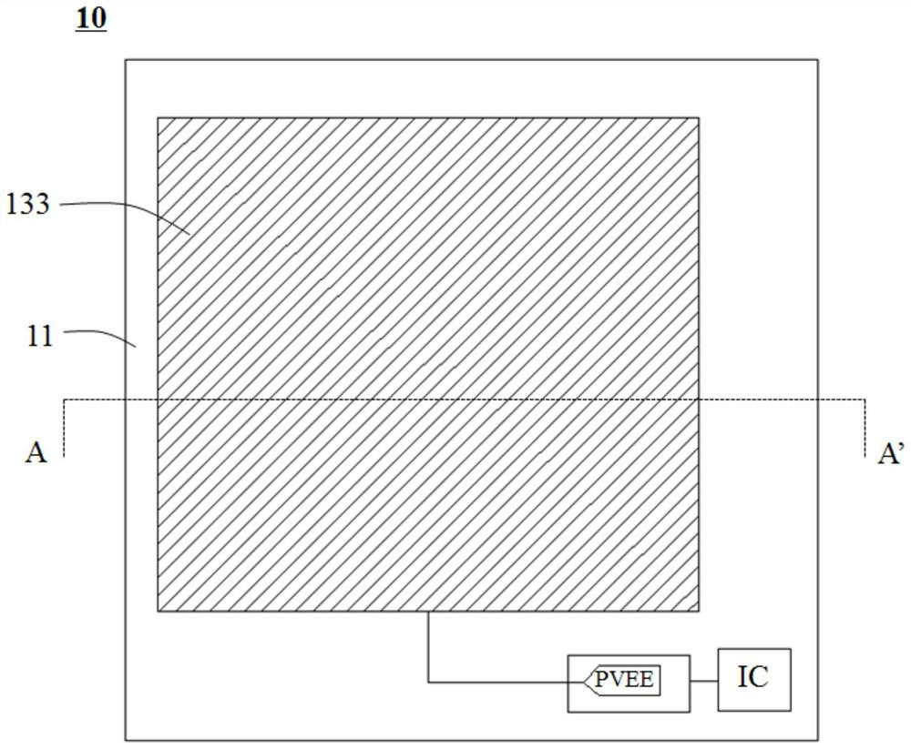
When the size of the OLED display is small, the voltage drop of the cathode can be ignored; but when the size of the display is large, the voltage drop of the cathode cannot be ignored at this time, and it is directly reflected on the screen, which will cause the problem of uneven display brightness.

Method used


Image

  • Display panel, display device and manufacturing method of array substrate
  • Display panel, display device and manufacturing method of array substrate
  • Display panel, display device and manufacturing method of array substrate

Examples


Embodiment Construction

[0026] In order to make the above objects, features and advantages of the present invention more comprehensible, the present invention will be further described below in conjunction with the accompanying drawings and embodiments.

[0027] It should be noted that in the following description, specific details are set forth in order to fully understand the present invention. However, the present invention can be implemented in many other ways than those described here, and those skilled in the art can make similar extensions without departing from the connotation of the present invention. Accordingly, the present invention is not limited to the specific embodiments disclosed below.

[0028] Terms used in the embodiments of the present invention are only for the purpose of describing specific embodiments, and are not intended to limit the present invention. As used in the embodiments of the present invention and the appended claims, the singular forms "a", "said" and "the" are a...


PUM

PropertyMeasurementUnit
Melting temperatureaaaaaaaaaa

Abstract

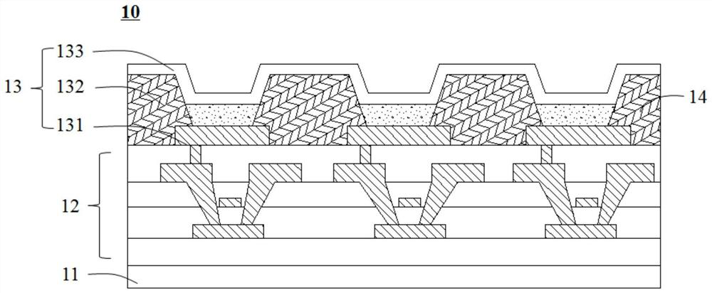
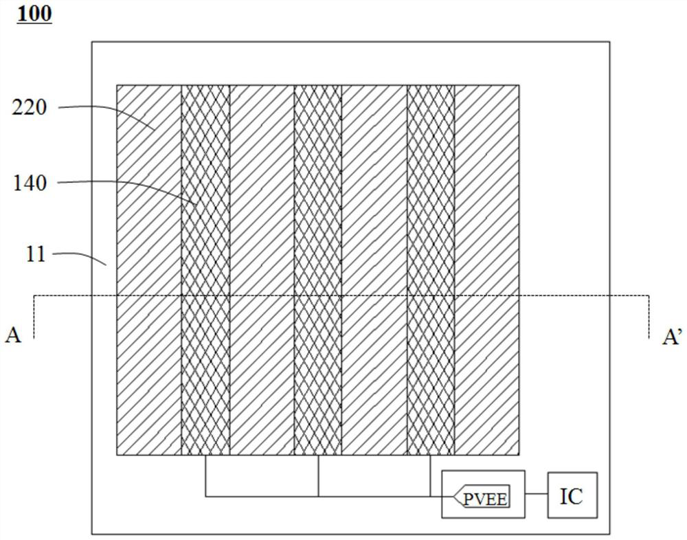
The invention discloses a display panel, a display device and a manufacturing method of an array substrate. The display panel comprises: a substrate, an array layer, an anode, a pixel definition layer, a light-emitting layer and a cathode that are located on one side of the substrate and are sequentially arranged; and the pixel definition layer comprises a first opening exposing the anode; the light-emitting layer is at least partially arranged in the first opening; and the cathode comprises a first gap located in a non-first opening area. the display panel further comprises a first electric conductor covering the first gap. The resistivity of the first conductor is smaller than that of the cathode. The invention further provides a display device comprising the display panel structure and a manufacturing method of an array substrate which can be applied to the display panel. According to the invention, the difference between the magnitude of current transmitted to the center of the cathode driving signal and the magnitude of current transmitted to the edge of the cathode driving signal is small, so that the problem of uneven display caused by low brightness of the center area of the screen is solved, and the display panel has a better display effect.

Description

technical field [0001] The present invention relates to the field of display technology, in particular to a display panel, a display device including the display panel, and a method for manufacturing an array substrate applicable to the display panel. Background technique [0002] Organic light-emitting diode display devices have many advantages such as white light emission, low driving voltage, high luminous efficiency, short response time, high definition and contrast, large viewing angle, wide operating temperature range, flexible large-area display and full-color display, and are currently mainstream. display technology. [0003] Top-emitting OLED is currently the mainstream OLED panel display technology. Its unique microcavity structure endows top-emitting OLED with advantages such as high aperture ratio, high color purity, and wide color gamut. The top-emitting OLED is composed of a fully reflective anode (RE) and a transflective cathode (TCE). The cathode is usually ...

Claims


Application Information

Patent Timeline
IPC IPC(8): H01L51/52H01L27/32H01L51/56
CPCH10K59/1315H10K59/131H10K50/86H10K71/00
Inventor 刘操霍思涛
Owner SHANGHAI TIANMA MICRO ELECTRONICS CO LTD
Learn More