Deep underground tunnel ventilation shaft supporting structure

A technology for tunnel ventilation and support structure, applied in shaft equipment, shaft lining, drainage and other directions, can solve the problems of rapid change, increased construction difficulty, difficult construction, etc., and achieves small self-weight, saving construction period, construction convenience and timeliness significant effect

Pending Publication Date: 2021-05-14
中国人民解放军军事科学院国防工程研究院工程防护研究所
View PDF11 Cites 3 Cited by
  • Summary
  • Abstract
  • Description
  • Claims
  • Application Information

AI Technical Summary

Problems solved by technology

However, in areas with complex geological conditions, especially in areas where the surrounding rock is severely weathered, joints and fissures are developed, the rock mass is relatively broken, and the rock mass is rich in water, if there is water gushing in the well during excavation, it will bring great difficulties to the construction.
In addition, the surrounding rock is soft rock, which is unstable, changes rapidly, easily softens and collapses when exposed to water, and is prone to large deformation, which is another major problem in shaft construction.
For water-rich areas and complex geological conditions, the initial strength of the traditional anchor-sprayed support is slow, and the construction difficulty is increased, which greatly increases the safety hazard

Method used


Image

  • Deep underground tunnel ventilation shaft supporting structure
  • Deep underground tunnel ventilation shaft supporting structure
  • Deep underground tunnel ventilation shaft supporting structure

Examples


Embodiment Construction

[0027] The technical solutions of the present invention will be clearly and completely described below in conjunction with the drawings in this specification. It should be noted that the described embodiments are only some of the embodiments of the present invention, not all of them. Based on the embodiments of the present invention, all other embodiments obtained by persons of ordinary skill in the art without creative efforts fall within the protection scope of the present invention.

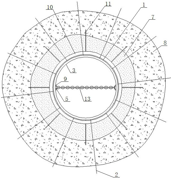
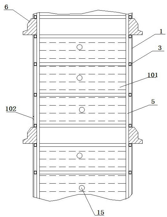
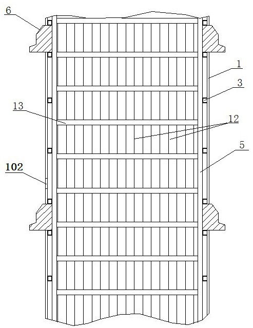
[0028] Such as Figure 1 to Figure 6 As shown, a deep underground tunnel ventilation shaft support structure, including the middle partition wall, steel column 5, corrugated steel support 1, concrete reinforcement ring 6 and polymer grouting layer 7, the corrugated steel support 1. It is a vertical cylindrical structure as a whole, which is composed of a plurality of arc-shaped corrugated steel plates 101. The arc-shaped corrugated steel plates 101 are generally rectangular plate-shaped struct...


PUM


Abstract

The invention provides a deep underground tunnel ventilation shaft supporting structure. The deep underground tunnel ventilation shaft supporting structure comprises a middle partition wall, steel stand columns, corrugated steel supports, concrete reinforcing rings and a high-molecular polymer grouting layer. The whole corrugated steel supports are of a vertical cylindrical structure, a plurality of corrugated steel supports are coaxial and are vertically arranged at intervals, the concrete reinforcing rings are arranged between the adjacent corrugated steel supports, the concrete reinforcing rings and the corrugated steel supports are coaxial, the middle partition wall is vertically arranged in the middle positions in the plurality of corrugated steel supports, and the left end and the right end of the middle partition wall are each provided with one vertical steel stand column and are fixedly connected with a steel ring beam through the steel stand columns. The high-molecular polymer grouting layer is arranged between the corrugated steel supports and shaft wall surrounding rock. The deep underground tunnel ventilation shaft supporting structure can be closed in time to form a ring, construction is convenient, surrounding rock can be rapidly closed and grouted on a complex surrounding rock section, surrounding rock collapse and deformation are restrained, and high safety, timeliness and economic efficiency are achieved.

Description

technical field [0001] The invention relates to the field of surrounding rock support in underground spaces, in particular to the support technology for ventilation shafts, in particular to a support structure for ventilation shafts in deep underground tunnels. Background technique [0002] During the construction and operation of deep underground tunnels, it is necessary to excavate a shaft with a large diameter vertically downward from the surface for personnel access, tunnel ventilation and other functions, which play an important role in both the construction period and the operation period. If the shaft is constructed using the front shaft method, construction can be started at both ends of the tunnel at the same time, which can solve the problem of ventilation in the main tunnel and the problem of early penetration of key lines, and speed up the overall construction progress of the project. According to the requirements of relevant design specifications, the diameter o...

Claims


Application Information

Patent Timeline
IPC IPC(8): E21D5/11E21F16/00E21F17/103
CPCE21D5/11E21F16/00E21F17/103
Inventor 郭鹏孔福利石晓燕范俊奇刘恩来陈安敏
Owner 中国人民解放军军事科学院国防工程研究院工程防护研究所
Why Eureka
Try Eureka