Eureka AIR delivers breakthrough ideas for toughest innovation challenges, trusted by R&D personnel around the world.

Tab welding method and tab welding device

A tab welding and tab technology, applied in auxiliary devices, welding equipment, welding equipment, etc., can solve the problems of reducing the effective volume utilization rate of the battery, the weak connection between the tab and the cover plate, and reducing the energy density of the battery. Improve the effective volume utilization rate and energy density, avoid weak connection or even virtual welding, and reduce the effect of pressing down the moving distance

Active Publication Date: 2021-05-14
HUBEI JINQUAN NEW MATERIALS CO LTD
View PDF6 Cites 5 Cited by
  • Summary
  • Abstract
  • Description
  • Claims
  • Application Information

AI Technical Summary

Problems solved by technology

[0003] However, when the tabs are welded under pressure, due to the unevenness of each layer of tabs, there may be a problem that the tabs of the upper layer are torn when welding multi-layer tabs, so that the tabs are not connected to the cover plate after welding. Problems such as firmness or even weak welding lead to abnormal internal resistance of the battery or the risk of disconnection of tabs from the cover
[0004] In order to solve the above problems, the current welding process between the tab and the cover plate in the industry is generally to pre-weld the tab and the connecting piece, and then weld the connecting piece and the cover plate, and increase the connection between the tab and the cover through the connecting piece. The connection strength of the board, but increases the weight of the extra process and the battery, and also reduces the effective volume utilization of the battery, thereby reducing the energy density of the battery

Method used


Image

  • Tab welding method and tab welding device
  • Tab welding method and tab welding device
  • Tab welding method and tab welding device

Examples


Embodiment Construction

[0040] In order to make the technical problems solved by the present invention, the technical solutions adopted and the technical effects achieved clearer, the technical solutions of the embodiments of the present invention will be further described in detail below in conjunction with the accompanying drawings. Obviously, the described embodiments are only the technical solutions of the present invention. Some, but not all, embodiments. Based on the embodiments of the present invention, all other embodiments obtained by those skilled in the art without creative efforts fall within the protection scope of the present invention.

[0041] In the description of the present invention, unless otherwise clearly specified and limited, the terms "connected", "connected" and "fixed" should be understood in a broad sense, for example, it can be a fixed connection, a detachable connection, or an integrated ; It can be a mechanical connection or an electrical connection; it can be a direct...


PUM


Abstract

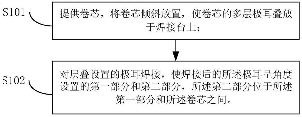
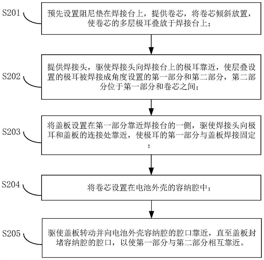
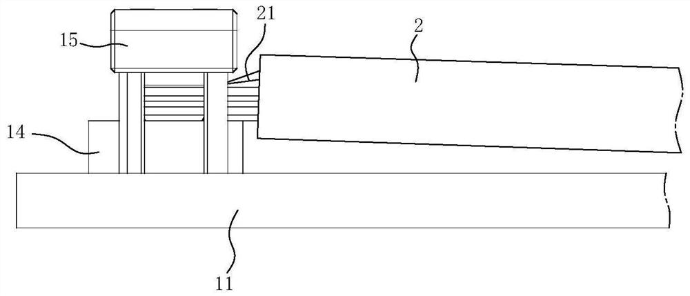
The invention relates to the technical field of batteries, and particularly discloses a tab welding method and a tab welding device. The tab welding method comprises the following steps of providing a roll core, obliquely placing the roll core, and stacking a plurality of layers of tabs of the roll core on a welding table; and welding the stacked tabs to enable the welded tabs to form first parts and second parts at angles, wherein the second parts are located between the first parts and the roll core. According to the tab welding method, the friction force and the pressing movement distance when the tab on the upper layer is welded and pressed down can be reduced, the defect that the tab on the upper layer is torn due to excessive displacement can be overcome, the problems that the tabs and a cover plate are not firmly connected after welding, even insufficient welding and the like are solved, therefore, the risks that the internal resistance of a battery is abnormal or the tabs are disconnected from the cover plate is avoided, the fracture defect and the untight attachment defect of the tabs can be reduced, a connecting piece is not needed, an additional process and the weight of the battery are prevented form being increased, and the effective volume utilization rate and the energy density of the battery are improved.

Description

technical field [0001] The invention relates to the technical field of batteries, in particular to a tab welding method and a tab welding device. Background technique [0002] With the development of new energy vehicles, the market demand for automotive power batteries is increasing, and the requirements are getting higher and higher. In the production process of the battery, how to improve the processing technology of each component of the battery has always been a key link in the production of the battery, especially the processing technology of the tabs of the battery winding core. In the actual tab processing process, the multi-layer tab of the winding core needs to be processed into one layer, and then connected to the cover plate to form the electrode of the battery. [0003] However, when the tabs are welded under pressure, due to the unevenness of each layer of tabs, there may be a problem that the tabs of the upper layer are torn when welding multi-layer tabs, so t...

Claims


Application Information

Patent Timeline
Patent Type & Authority Applications(China)
IPC IPC(8): B23K37/047B23K31/02H01M50/528H01M50/531H01M10/04
CPCB23K37/047B23K31/02H01M10/0431Y02E60/10Y02P70/50
Inventor 赵仕绪郭家豪吴磊杜双龙吕正中刘金成
Owner HUBEI JINQUAN NEW MATERIALS CO LTD
Why Eureka
Eureka Blog
Learn More