Eureka AIR delivers breakthrough ideas for toughest innovation challenges, trusted by R&D personnel around the world.

Plate type heat exchanger with asymmetric channels

A plate heat exchanger, asymmetric technology, applied in the direction of heat exchanger type, indirect heat exchanger, heat exchange equipment, etc., can solve the problem that the heat exchange performance and pressure bearing effect of the plate heat exchanger cannot be balanced, and achieve long-term Heat transfer stability, improved pressure bearing capacity, and improved heat transfer performance

Pending Publication Date: 2020-06-12
WEYEE HEAT EXCHANGER CO LTD
View PDF0 Cites 2 Cited by
  • Summary
  • Abstract
  • Description
  • Claims
  • Application Information

AI Technical Summary

Problems solved by technology

[0004] In order to solve the problem that the heat exchange performance and the pressure bearing effect of the existing plate heat exchanger cannot be balanced, the present invention provides a plate heat exchanger with asymmetric channels, the heat exchanger passes Several evenly distributed grooves are set on the valley to form asymmetric channels with different volumes on both sides of the second plate to increase heat transfer performance, and the grooves are set so that the ridges of the second plate are located on two adjacent sides. Between the two grooves, the slopes on both sides of the ridges and the slopes on both sides of the grooves in contact with each other effectively increase the welding area and enhance the pressure bearing effect of the heat exchanger, so that the heat transfer performance and pressure bearing effect are taken into account.

Method used


Image

  • Plate type heat exchanger with asymmetric channels
  • Plate type heat exchanger with asymmetric channels
  • Plate type heat exchanger with asymmetric channels

Examples


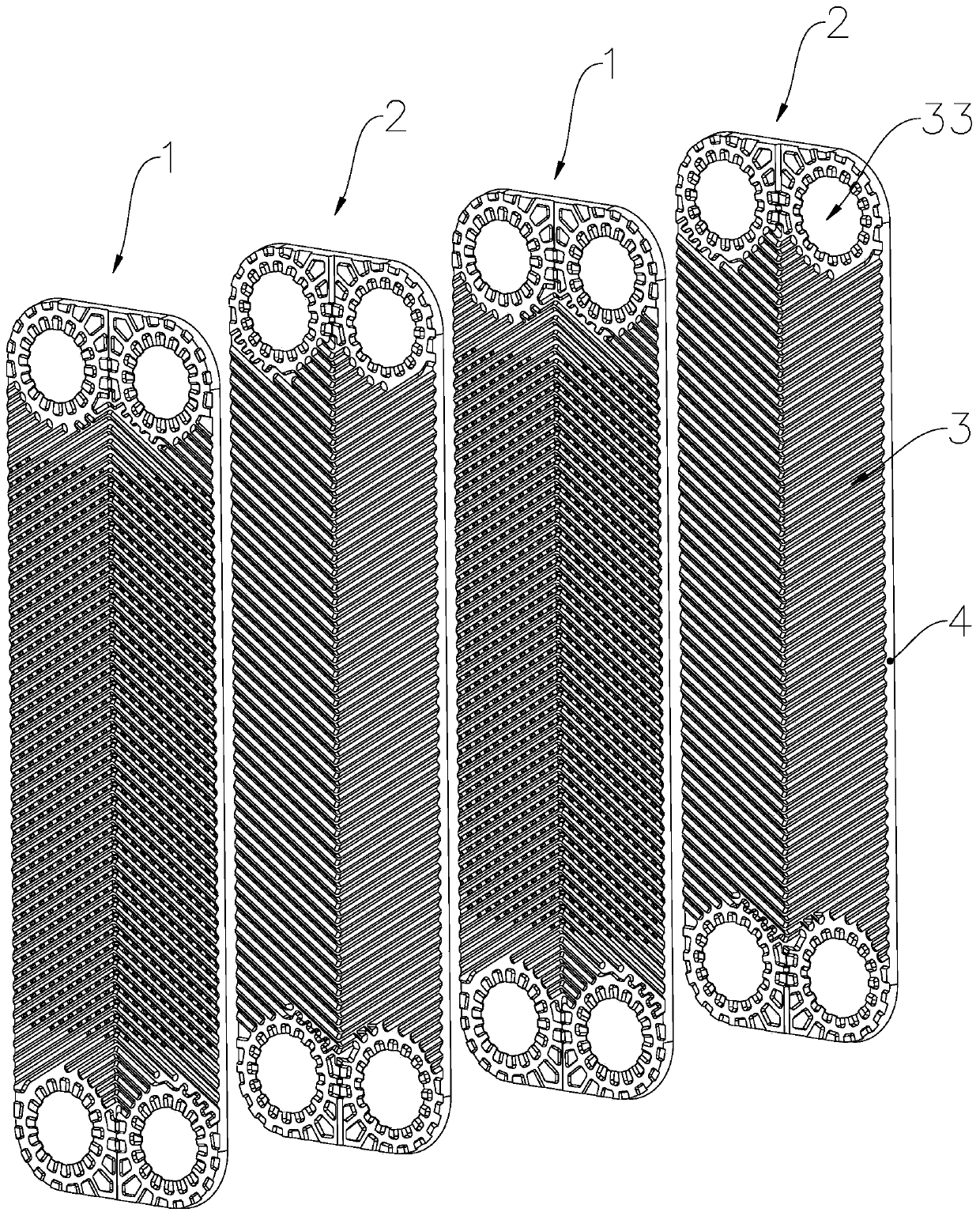
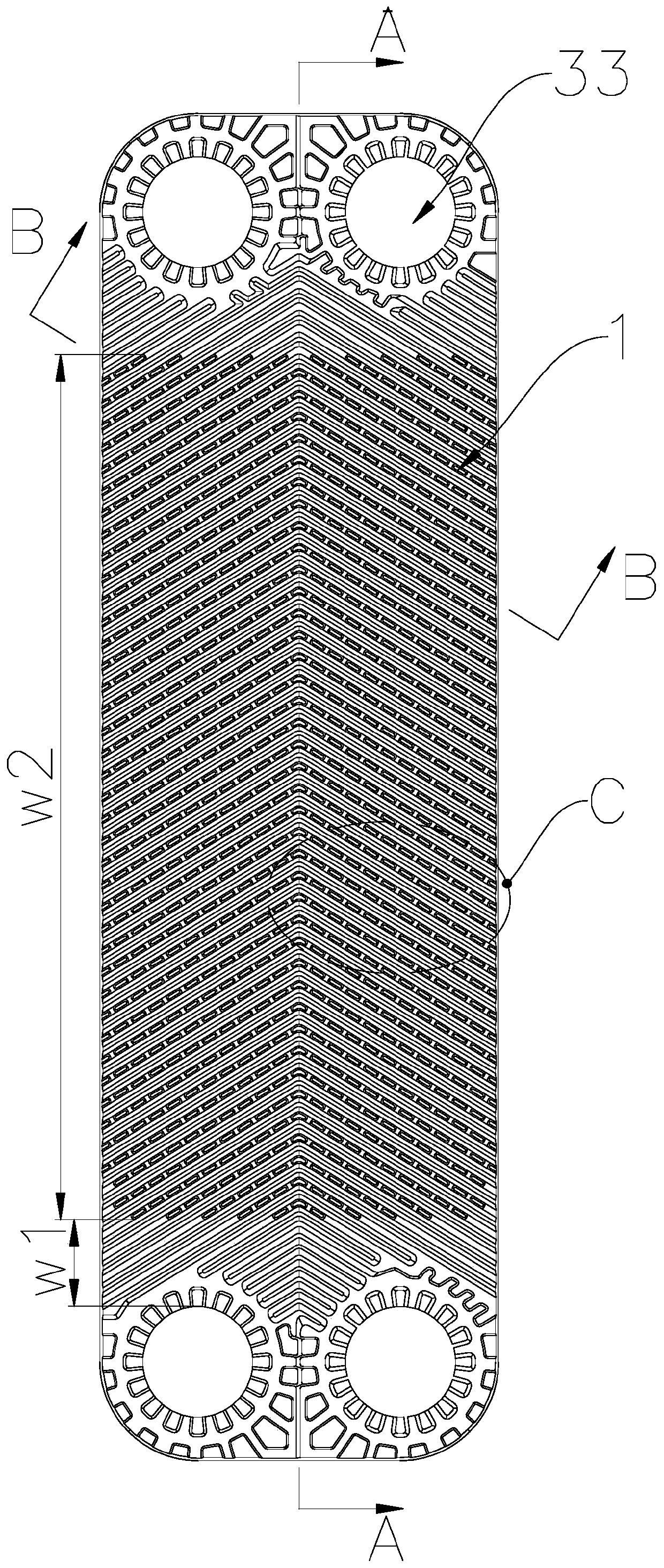
Embodiment Construction

[0027] The present invention is described in further detail now in conjunction with accompanying drawing. These drawings are all simplified schematic diagrams, which only illustrate the basic structure of the present invention in a schematic manner, so they only show the configurations related to the present invention.

[0028] A plate heat exchanger with asymmetric channels, such as figure 1 , figure 2 , image 3 , Figure 5 with Figure 6 As shown, it includes a plurality of heat exchange plates stacked to form heat exchange channels, the heat exchange plates are alternately arranged first plates 1 and second plates 2, first plates 1 and second plates 2 Both include a main panel 3 and surrounding baffles 4, the main panel 3 is provided with several ridges 31, and valleys 32 are formed between adjacent ridges 31, and several ridges 32 are evenly distributed on the valleys 32 of the first plate 1. The groove 321 forms asymmetric channels with different volumes on both si...


PUM


Abstract

The invention relates to the technical field of heat exchangers, in particular to a plate type heat exchanger with asymmetric channels. The plate type heat exchanger comprises a plurality of heat exchange plates stacked to form heat exchange channels, the heat exchange plates are first plates and second plates which are alternately arranged, the first plates and the second plates both comprise a main panel and surrounding baffles, a plurality of convex ridges are arranged on the main panel, a concave valley is formed between every two adjacent convex ridges, and a plurality of grooves are evenly distributed in the concave valley of the first plates, so that asymmetric channels with different volumes are formed in the two sides of the second plates. According to the heat exchanger, the multiple evenly-distributed grooves are formed in the valley of the first plates, asymmetric channels with different volumes are formed in the two sides of the second plates, the heat exchange performanceis improved, due to the arrangement of the grooves, the convex ridges of the second plates are clamped between every two adjacent grooves, the inclined planes on two sides of the convex ridges and the inclined planes on two sides of the grooves which are in contact with each other effectively increase the welding area, the pressure-bearing effect of the heat exchanger is enhanced, and the heat exchange performance and the pressure-bearing effect are both considered.

Description

technical field [0001] The invention relates to the technical field of heat exchangers, in particular to a plate heat exchanger with asymmetric channels. Background technique [0002] The brazed plate heat exchanger is a high-efficiency heat exchanger made by stacking a series of metal sheets with a certain corrugated shape and brazing. Channels are formed between the various plates, and heat exchange is performed through the plates. Compared with conventional shell-and-tube heat exchangers, its heat transfer coefficient is much higher under the same flow resistance and pump power consumption, and it tends to replace shell-and-tube heat exchangers within the applicable range. [0003] The heat transfer performance and pressure bearing performance of the brazed plate heat exchanger are two important technical indicators of the product. Under the premise of ensuring the customer's design conditions, the heat transfer performance of the heat exchanger should be improved as mu...

Claims


Application Information

Patent Timeline
Patent Type & Authority Applications(China)
IPC IPC(8): F28D9/00F28F3/04F28F3/08
CPCF28D9/005F28F3/048F28F3/083
Inventor 施吉璐韩维哲陈天鹏戚邗云张雯
Owner WEYEE HEAT EXCHANGER CO LTD
Why Eureka
Eureka Blog
Learn More